SFI SYSTEM(w/ Canister Pump Module), Diagnostic DTC:P0367, P0368, P0392, P0393
| DTC Code | DTC Name |
|---|---|
| P0367 | Camshaft Position Sensor "B" Circuit Low Input (Bank 1) |
| P0368 | Camshaft Position Sensor "B" Circuit High Input (Bank 1) |
| P0392 | Camshaft Position Sensor "B" Circuit Low Input (Bank 2) |
| P0393 | Camshaft Position Sensor "B" Circuit High Input (Bank 2) |
DESCRIPTION
Refer to DTC P0365.
| DTC No. | Detection Item | DTC Detection Condition | Trouble Area | MIL | Memory |
|---|---|---|---|---|---|
| P0367 | Camshaft Position Sensor "B" Circuit Low Input (Bank 1) | The output voltage of the exhaust VVT sensor (bank 1) is less than 0.3 V for 4 seconds (1 trip detection logic). |
|
Comes on | DTC stored |
| P0368 | Camshaft Position Sensor "B" Circuit High Input (Bank 1) | The output voltage of the exhaust VVT sensor (bank 1) is higher than 4.7 V for 4 seconds (1 trip detection logic). |
|
Comes on | DTC stored |
| P0392 | Camshaft Position Sensor "B" Circuit Low Input (Bank 2) | The output voltage of the exhaust VVT sensor (bank 2) is less than 0.3 V for 4 seconds (1 trip detection logic). |
|
Comes on | DTC stored |
| P0393 | Camshaft Position Sensor "B" Circuit High Input (Bank 2) | The output voltage of the exhaust VVT sensor (bank 2) is higher than 4.7 V for 4 seconds (1 trip detection logic). |
|
Comes on | DTC stored |
-
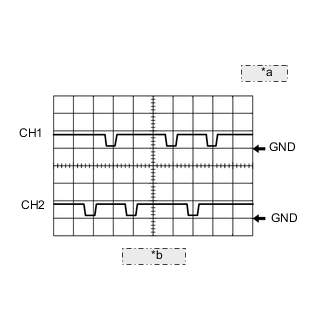
*a 5 V/DIV. *b 20 ms./DIV. Reference: Inspection using an oscilloscope
Tech Tips
-
The correct waveform is as shown.
-
The wavelength becomes shorter as the engine speed increases.
ECM Terminal Name CH1: Between EV1+ and EV1-
CH2: Between EV2+ and EV2-
Tester Range 5 V/DIV., 20 ms./DIV. Condition Idling with warm engine -
MONITOR DESCRIPTION
If the output voltage transmitted by the vvt sensor remains low or high, the ECM interprets this as a malfunction in the sensor circuit, illuminates the MIL and stores a DTC.
MONITOR STRATEGY
| Required Sensors/Components (Main) | VVT sensor (for exhaust camshaft) |
| Required Sensors/Components (Related) | Crankshaft position sensor |
| Frequency of Operation | Continuous |
CONFIRMATION DRIVING PATTERN
-
Connect the GTS to the DLC3.
-
Turn the engine switch on (IG).
-
Turn the GTS on.
-
Clear the DTCs (even if no DTCs are stored, perform the clear DTC procedure).
-
Turn the engine switch off and wait for at least 30 seconds.
-
Turn the engine switch on (IG).
-
Turn the GTS on.
-
Start the engine.
-
Idle the engine for 10 seconds or more [A].
-
Enter the following menus: Powertrain / Engine / Trouble Codes [B].
-
Read the pending DTCs.
Tech Tips
-
If a pending DTC is output, the system is malfunctioning.
-
If a pending DTC is not output, perform the following procedure.
-
-
Enter the following menus: Powertrain / Engine / Utility / All Readiness.
-
Input the DTC: P0367, P0368, P0392 or P0393.
-
Check the DTC judgment result.
GTS Display Description NORMAL
-
DTC judgment completed
-
System normal
ABNORMAL
-
DTC judgment completed
-
System abnormal
INCOMPLETE
-
DTC judgment not completed
-
Perform driving pattern after confirming DTC enabling conditions
N/A
-
Unable to perform DTC judgment
-
Number of DTCs which do not fulfill DTC preconditions has reached ECU memory limit
Tech Tips
-
If the judgment result shows NORMAL, the system is normal.
-
If the judgment result shows ABNORMAL, the system has a malfunction.
-
If the judgment result shows INCOMPLETE or N/A, perform steps [A] and [B] again.
-
CAUTION / NOTICE / HINT
Tech Tips
-
If no problem is found through this diagnostic troubleshooting procedure, there may be a mechanical problem with the engine.
-
Bank 1 refers to the bank that includes the No. 1 cylinder*.
*: The No. 1 cylinder is the cylinder which is farthest from the transmission.
-
Bank 2 refers to the bank that does not include the No. 1 cylinder.
-
Read freeze frame data using the GTS. The ECM records vehicle and driving condition information as freeze frame data the moment a DTC is stored. When troubleshooting, freeze frame data can help determine if the vehicle was moving or stationary, if the engine was warmed up or not, if the air fuel ratio was lean or rich, and other data from the time the malfunction occurred.
PROCEDURE
-
CHECK TERMINAL VOLTAGE (POWER SOURCE OF VVT SENSOR (FOR EXHAUST CAMSHAFT))
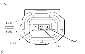
*a Front view of wire harness connector
(to VVT Sensor (for Exhaust Camshaft))
*b Bank 1 *c Bank 2
-
Disconnect the VVT sensor (for exhaust camshaft) connector.
-
Turn the engine switch on (IG).
-
Measure the voltage according to the value(s) in the table below.
Standard Voltage Tester Connection Switch Condition Specified Condition G58-3 (VC2) - Body ground Engine switch on (IG) 4.5 to 5.5 V G58-1 (EX+) - Body ground Engine switch on (IG) 4.5 to 5.5 V G59-3 (VC2) - Body ground Engine switch on (IG) 3.0 to 5.5 V G59-1 (EX+) - Body ground Engine switch on (IG) 3.0 to 5.5 V -
Turn the engine switch off and wait for at least 30 seconds.
-
Measure the resistance according to the value(s) in the table below.
Standard Resistance Tester Connection Switch Condition Specified Condition G58-3(VC2) - G58-1(EX+) Engine switch off 1.425 to 1.575 kΩ G59-3(VC2) - G59-1(EX+) Engine switch off 1.425 to 1.575 kΩ G58-2(EX-) - Body ground Always Below 1 Ω G59-2(EX-) - Body ground Always Below 1 Ω Result Proceed to OK NG
OK 
REPLACE VVT SENSOR (FOR EXHAUST CAMSHAFT)
NG 
-
-
CHECK HARNESS AND CONNECTOR (VVT SENSOR (FOR EXHAUST CAMSHAFT) - ECM)
-
Disconnect the VVT sensor (for exhaust camshaft) connectors.
-
Disconnect the ECM connector.
-
Disconnect the crankshaft position sensor connector.
-
Disconnect the VVT sensor (for intake camshaft) connectors.
-
Disconnect the camshaft position sensor connector.
-
Disconnect the canister pump module connector.
-
Measure the resistance according to the value(s) in the table below.
Standard Resistance Tester Connection Condition Specified Condition G58-3 (VC2) - G42-90 (VC) Always Below 1 Ω G59-3 (VC2) - G42-90 (VC) Always Below 1 Ω G58-1 (EX+) - G42-137 (EV1+) Always Below 1 Ω G58-2 (EX-) - G42-105 (EV1-) Always Below 1 Ω G59-1 (EX+) - G42-136 (EV2+) Always Below 1 Ω G59-2 (EX-) - G42-104 (EV2-) Always Below 1 Ω G58-3 (VC2), G59-3 (VC2) or G42-90 (VC) - Body ground and other terminals Always 10 kΩ or higher G58-1 (EX+) or G42-137 (EV1+) - Body ground and other terminals Always 10 kΩ or higher G58-2 (EX-) or G42-105 (EV1-) - Body ground and other terminals Always 10 kΩ or higher G59-1 (EX+) or G42-136 (EV2+) - Body ground and other terminals Always 10 kΩ or higher G59-2 (EX-) or G42-104 (EV2-) - Body ground and other terminals Always 10 kΩ or higher Result Proceed to OK NG
OK
REPLACE ECM Click here
NG
REPAIR OR REPLACE HARNESS OR CONNECTOR
-