SFI SYSTEM(w/o Canister Pump Module) Exhaust Gas Control Circuit
CAUTION / NOTICE / HINT
CAUTION:
Do no perform the Active Test with the exhaust pipe gas control actuator sub-assembly removed.
Tech Tips
-
Read freeze frame data using the GTS. The ECM records vehicle and driving condition information as freeze frame data the moment a DTC is stored. When troubleshooting, freeze frame data can help determine if the vehicle was moving or stationary, if the engine was warmed up or not, if the air fuel ratio was lean or rich, and other data from the time the malfunction occurred.
-
The connector for the exhaust pipe gas control actuator sub-assembly can be connected on either the left or right side.
When installing the wire harness after performing repairs, install it at the specified position.
-
Connect the No. 1 exhaust change valve driver to the No. 1 exhaust pipe gas control actuator sub-assembly connected to the white wires with protective coating
-
Connect the No. 2 exhaust change valve driver to the No. 2 exhaust pipe gas control actuator sub-assembly connected to the black wires with protective coating.
-
During troubleshooting, refer to the illustration below to check the colors of the profective coating of the exhaust pipe gas control actuator sub-assembly wire harness.
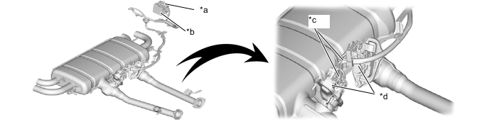
*a No. 1 exhaust change valve driver *b No. 2 exhaust change valve driver *c Wire harness (white or black wires with protective coating) *d Exhaust pipe gas control actuator sub-assembly
(No. 1: white wires with protective coating)
(No. 2: black wires with protective coating)
PROCEDURE
-
CHECK DTC OUTPUT
-
Connect the GTS to the DLC3.
-
Turn the engine switch on (IG).
-
Turn the GTS on.
-
Enter the following menus: Powertrain / Engine / Trouble Codes.
Powertrain > Engine > Trouble Codes -
Read the DTCs.
Result Result Proceed to DTCs are not output A DTC is output B
B 
GO TO DTC CHART Click here
A 
-
-
PERFORM ACTIVE TEST USING GTS
CAUTION:
Be careful of the exhaust gas, exhaust pipes and surrounding areas as they become extremely hot.
-
Connect the GTS to the DLC3.
-
Turn the engine switch on (IG).
-
Turn the GTS on.
-
Enter the following menus: Powertrain / Engine / Active Test / Control the Exhaust Exterior Valve Angle.
Powertrain > Engine > Active TestTester Display Control the Exhaust Exterior Valve Angle -
Perform the Active Test to operate the exhaust change valve.
OK The exhaust gas output switches from the inner left and right tailpipes to the inner and outer left and right tailpipes. Result Proceed to OK NG
OK
CHECK FOR INTERMITTENT PROBLEMS Click here
NG
-
-
CHECK IF DTC OUTPUT RECURS
-
Switch connector M2, M4 and M1, M3 on the exhaust pipe gas control actuator sub-assembly.
-
Connect the GTS to the DLC3.
-
Turn the engine switch on (IG).
-
Turn the GTS on.
-
Enter the following menus: Powertrain / Engine / Active Test / Control the Exhaust Exterior Valve Angle.
Powertrain > Engine > Active TestTester Display Control the Exhaust Exterior Valve Angle -
Perform the Active Test to operate the exhaust change valve.
Result Result Proceed to Location of malfunction does not change A Location of malfunction changes B
B
REPLACE EXHAUST PIPE GAS CONTROL ACTUATOR SUB-ASSEMBLY Click here
A
-
-
CHECK IF DTC OUTPUT RECURS
-
Switch connector X80 and X81 on the exhaust change valve driver.
Tech Tips
The wire harnesses are different lengths. Therefore, remove the exhaust change valve driver and change the position of the connector.
-
Connect the GTS to the DLC3.
-
Turn the engine switch on (IG).
-
Turn the GTS on.
-
Enter the following menus: Powertrain / Engine / Active Test / Control the Exhaust Exterior Valve Angle.
Powertrain > Engine > Active TestTester Display Control the Exhaust Exterior Valve Angle Result Result Proceed to Location of malfunction does not change A Location of malfunction changes B
A
REPAIR OR REPLACE HARNESS OR CONNECTOR (EXHAUST CHANGE VALVE DRIVER - EXHAUST PIPE GAS CONTROL ACTUATOR SUB-ASSEMBLY)
B
REPLACE EXHAUST CHANGE VALVE DRIVER Click here
-