HAZARD WARNING SWITCH REMOVAL
CAUTION / NOTICE / HINT
The necessary procedures (adjustment, calibration, initialization or registration) that must be performed after parts are removed and installed, or replaced during hazard warning signal switch assembly removal/installation are shown below.
| Replaced Part or Performed Procedure | Necessary Procedure | Effect/Inoperative Function when Necessary Procedure not Performed | Link |
|---|---|---|---|
| Disconnect cable from negative battery terminal | Perform steering sensor zero point calibration | Lane departure alert system (w/ Steering Control) | |
| Pre-collision system | |||
| Memorize steering angle neutral point | Parking assist monitor system |
CAUTION:
Some of these service operations affect the SRS airbag system. Read the precautionary notices concerning the SRS airbag system before servicing.
PROCEDURE
-
REMOVE INSTRUMENT PANEL SAFETY PAD SUB-ASSEMBLY
-
REMOVE NO. 1 SIDE DEFROSTER NOZZLE DUCT
-
REMOVE NO. 2 SIDE DEFROSTER NOZZLE DUCT
-
REMOVE DEFROSTER NOZZLE ASSEMBLY
-
REMOVE METER MIRROR SUB-ASSEMBLY (w/ Headup Display)
-
REMOVE NO. 1 HEATER TO REGISTER DUCT SUB-ASSEMBLY
-
REMOVE NO. 3 HEATER TO REGISTER DUCT SUB-ASSEMBLY
-
REMOVE NO. 2 HEATER TO REGISTER DUCT SUB-ASSEMBLY
-
REMOVE NO. 2 INSTRUMENT PANEL REGISTER ASSEMBLY
-
REMOVE HAZARD WARNING SIGNAL SWITCH ASSEMBLY
-
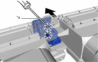
*a Protective Tape 
Remove in this Direction Using a screwdriver with its tip wrapped with protective tape, disengage the 2 claws and remove the hazard warning signal switch assembly as shown in the illustration.
-