HEADLIGHT ASSEMBLY(for Bulb Type Turn Signal Light) INSPECTION
PROCEDURE
-
INSPECT HEADLIGHT UNIT ASSEMBLY LH (w/ Automatic Headlight Beam Level Control System)
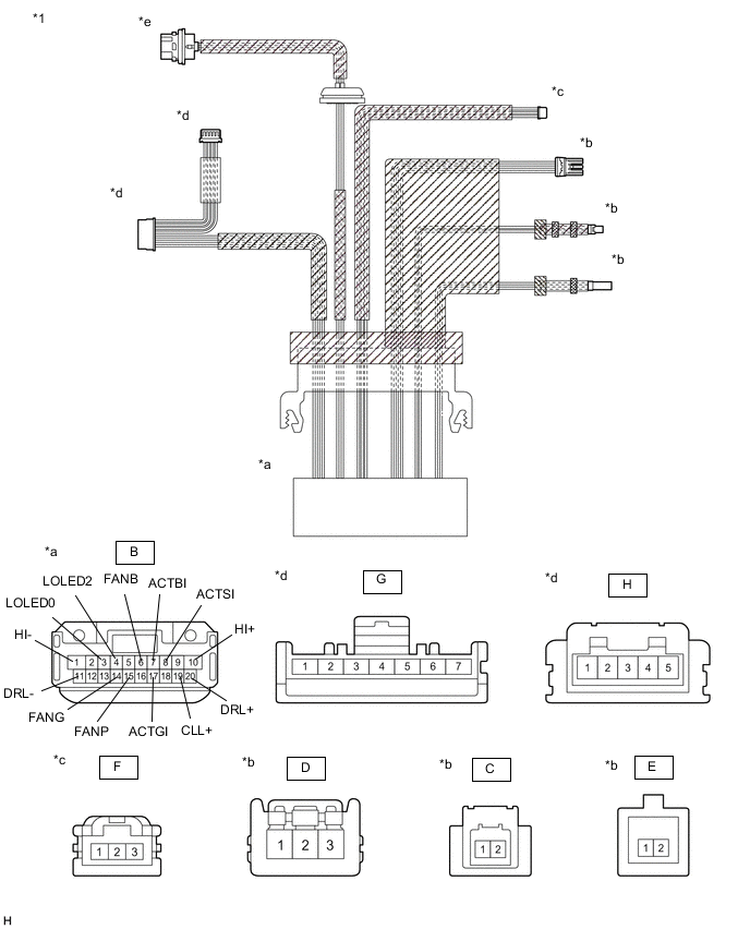
*1 Headlight Unit Assembly LH (Headlight Cord) - - *a Component without harness connected
(to Headlight ECU Sub-assembly LH)
*b Component without harness connected
(to Headlight LED Unit Assembly LH)
*c Component without harness connected
(to Headlight Leveling Motor LH)
*d Component without harness connected
(to No. 1 Headlight Clearance LED Unit LH)
*e Component without turn signal light installed
(to Turn Signal Light)
- -
-
Measure the resistance according to the value(s) in the table below.
-
Inspect the headlight leveling motor circuit.
Standard Resistance Tester Connection Condition Specified Condition B-7 (ACTBI) - F-1 Always Below 1 Ω B-8 (ACTSI) - F-2 Always Below 1 Ω B-17 (ACTGI) - F-3 Always Below 1 Ω If the result is not as specified, replace the headlight unit assembly LH (headlight cord).
-
Inspect the Lo/Hi beam circuit.
Standard Resistance Tester Connection Condition Specified Condition B-4 (LOLED2) - C-2 Always Below 1 Ω B-3 (LOLED0) - C-1 Always Below 1 Ω If the result is not as specified, replace the headlight unit assembly LH (headlight cord).
-
Inspect the Lo/Hi beam shade circuit.
Standard Resistance Tester Connection Condition Specified Condition B-10 (HI+) - E-1 Always Below 1 Ω B-1 (HI-) - E-2 Always Below 1 Ω If the result is not as specified, replace the headlight unit assembly LH (headlight cord).
-
Inspect the headlight fan circuit.
Standard Resistance Tester Connection Condition Specified Condition B-6 (FANB) - D-3 Always Below 1 Ω B-15 (FANP) - D-2 Always Below 1 Ω B-14 (FANG) - D-1 Always Below 1 Ω If the result is not as specified, replace the headlight unit assembly LH (headlight cord).
-
Inspect the clearance light/daytime running light input circuit.
Standard Resistance Tester Connection Condition Specified Condition B-20 (DRL+) - G-1 Always Below 1 Ω B-11 (DRL-) - G-3 Always Below 1 Ω B-19 (CLL+) - G-2 Always Below 1 Ω If the result is not as specified, replace the headlight unit assembly LH (headlight cord).
-
Inspect the clearance light/daytime running light output circuit.
Standard Resistance Tester Connection Condition Specified Condition G-4 - H-5 Always Below 1 Ω G-5 - H-4 Always Below 1 Ω G-6 - H-3 Always Below 1 Ω G-7 - H-1 Always Below 1 Ω If the result is not as specified, replace the headlight unit assembly LH (headlight cord).
-
-
-
INSPECT HEADLIGHT LED UNIT ASSEMBLY LH (w/ Automatic Headlight Beam Level Control System)
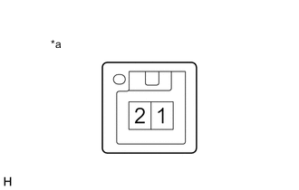
*a Component without harness connected
(Headlight LED Unit Assembly LH)
-
Apply battery voltage to the headlight LED unit assembly LH and check that the Lo/Hi beam shade operates.
OK Condition Specified Condition Battery positive (+) → Terminal 1
Battery negative (-) → Terminal 2
Operates normally If the result is not as specified, replace the headlight LED unit assembly LH.
-
-
INSPECT NO. 1 HEADLIGHT CLEARANCE LED UNIT LH (w/ Automatic Headlight Beam Level Control System)
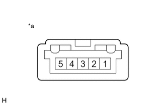
*a Component without harness connected
(No. 1 Headlight Clearance LED Unit LH)
-
Apply battery voltage to the No. 1 headlight clearance LED unit LH and check that the light illuminates.
OK Condition Specified Condition Battery positive (+) → Terminal 1
Battery negative (-) → Terminal 3
Clearance light/daytime running light illuminates If the result is not as specified, replace the No. 1 headlight clearance LED unit LH.
-
-
INSPECT HEADLIGHT UNIT ASSEMBLY RH (w/ Automatic Headlight Beam Level Control System)
*1 Headlight Unit Assembly RH (Headlight Cord) - - *a Component without harness connected
(to Headlight ECU Sub-assembly RH)
*b Component without harness connected
(to Headlight LED Unit Assembly RH)
*c Component without harness connected
(to Headlight Leveling Motor RH)
*d Component without harness connected
(to No. 1 Headlight Clearance LED Unit RH)
-
Measure the resistance according to the value(s) in the table below.
-
Inspect the headlight leveling motor circuit.
Standard Resistance Tester Connection Condition Specified Condition B-7 (ACTBI) - F-1 Always Below 1 Ω B-8 (ACTSI) - F-2 Always Below 1 Ω B-17 (ACTGI) - F-3 Always Below 1 Ω If the result is not as specified, replace the headlight unit assembly RH (headlight cord).
-
Inspect the Lo/Hi beam circuit.
Standard Resistance Tester Connection Condition Specified Condition B-4 (LOLED2) - C-2 Always Below 1 Ω B-3 (LOLED0) - C-1 Always Below 1 Ω If the result is not as specified, replace the headlight unit assembly RH (headlight cord).
-
Inspect the Lo/Hi beam shade circuit.
Standard Resistance Tester Connection Condition Specified Condition B-10 (HI+) - E-1 Always Below 1 Ω B-1 (HI-) - E-2 Always Below 1 Ω If the result is not as specified, replace the headlight unit assembly RH (headlight cord).
-
Inspect the headlight fan circuit.
Standard Resistance Tester Connection Condition Specified Condition B-6 (FANB) - D-3 Always Below 1 Ω B-15 (FANP) - D-2 Always Below 1 Ω B-14 (FANG) - D-1 Always Below 1 Ω If the result is not as specified, replace the headlight unit assembly RH (headlight cord).
-
Inspect the clearance light/daytime running light input circuit.
Standard Resistance Tester Connection Condition Specified Condition B-20 (DRL+) - G-1 Always Below 1 Ω B-11 (DRL-) - G-3 Always Below 1 Ω B-19 (CLL+) - G-2 Always Below 1 Ω If the result is not as specified, replace the headlight unit assembly RH (headlight cord).
-
Inspect the clearance light/daytime running light output circuit.
Standard Resistance Tester Connection Condition Specified Condition G-4 - H-5 Always Below 1 Ω G-5 - H-4 Always Below 1 Ω G-6 - H-3 Always Below 1 Ω G-7 - H-1 Always Below 1 Ω If the result is not as specified, replace the headlight unit assembly RH (headlight cord).
-
-
-
INSPECT HEADLIGHT LED UNIT ASSEMBLY RH (w/ Automatic Headlight Beam Level Control System)
*a Component without harness connected
(Headlight LED Unit Assembly RH)
-
Apply battery voltage to the headlight LED unit assembly RH and check that the Lo/Hi beam shade operates.
OK Condition Specified Condition Battery positive (+) → Terminal 1
Battery negative (-) → Terminal 2
Operates normally If the result is not as specified, replace the headlight LED unit assembly RH.
-
-
INSPECT NO. 1 HEADLIGHT CLEARANCE LED UNIT RH (w/ Automatic Headlight Beam Level Control System)
*a Component without harness connected
(No. 1 Headlight Clearance LED Unit RH)
-
Apply battery voltage to the No. 1 headlight clearance LED unit RH and check that the light illuminates.
OK Condition Specified Condition Battery positive (+) → Terminal 1
Battery negative (-) → Terminal 3
Clearance light/daytime running light illuminates If the result is not as specified, replace the No. 1 headlight clearance LED unit RH.
-
-
INSPECT HEADLIGHT UNIT ASSEMBLY LH (w/o Automatic Headlight Beam Level Control System)

*1 Headlight Unit Assembly LH (Headlight Cord) - - *a Component without harness connected
(to Wire Harness)
*b Component without harness connected
(to Headlight LED Unit Assembly LH)
*c Component without harness connected
(to Light Control ECU)
*d Component without harness connected
(to No. 1 Headlight Clearance LED Unit LH)
-
Measure the resistance according to the value(s) in the table below.
-
Inspect the Lo/Hi beam circuit.
Standard Resistance Tester Connection Condition Specified Condition A74-1 (E) - B-6 Always Below 1 Ω A74-2 (S) - B-12 Always Below 1 Ω A74-3 (LO) - B-7 Always Below 1 Ω B-4 - D-1 Always Below 1 Ω B-10 - D-2 Always Below 1 Ω If the result is not as specified, replace the headlight unit assembly LH (headlight cord).
-
Inspect the Lo/Hi beam shade circuit.
Standard Resistance Tester Connection Condition Specified Condition A74-1 (E) - E-2 Always Below 1 Ω A74-4 (SOL) - E-1 Always Below 1 Ω If the result is not as specified, replace the headlight unit assembly LH (headlight cord).
-
Inspect the headlight fan circuit.
Standard Resistance Tester Connection Condition Specified Condition B-2 - C-3 Always Below 1 Ω B-9 - C-2 Always Below 1 Ω B-11 - C-1 Always Below 1 Ω If the result is not as specified, replace the headlight unit assembly LH (headlight cord).
-
Inspect the clearance light/daytime running light input circuit.
Standard Resistance Tester Connection Condition Specified Condition A74-1 (E) - F-3 Always Below 1 Ω A74-5 (B) - F-2 Always Below 1 Ω A74-6 (B) - F-1 Always Below 1 Ω If the result is not as specified, replace the headlight unit assembly LH (headlight cord).
-
Inspect the clearance light/daytime running light output circuit.
Standard Resistance Tester Connection Condition Specified Condition F-4 - G-5 Always Below 1 Ω F-5 - G-4 Always Below 1 Ω F-6 - G-3 Always Below 1 Ω F-7 - G-1 Always Below 1 Ω If the result is not as specified, replace the headlight unit assembly LH (headlight cord).
-
-
-
INSPECT HEADLIGHT LED UNIT ASSEMBLY LH (w/o Automatic Headlight Beam Level Control System)
-
*a Component without harness connected
(Headlight LED Unit Assembly LH)
Apply battery voltage to the headlight LED unit assembly LH and check that the Lo/Hi beam shade operates.
OK Condition Specified Condition Battery positive (+) → Terminal 1
Battery negative (-) → Terminal 2
Operates normally If the result is not as specified, replace the headlight LED unit assembly LH.
-
-
INSPECT NO. 1 HEADLIGHT CLEARANCE LED UNIT LH (w/o Automatic Headlight Beam Level Control System)
*a Component without harness connected
(No. 1 Headlight Clearance LED Unit LH)
-
Apply battery voltage to the No. 1 headlight clearance LED unit LH and check that the light illuminates.
OK Condition Specified Condition Battery positive (+) → Terminal 1
Battery negative (-) → Terminal 3
Clearance light/daytime running light illuminates If the result is not as specified, replace the No. 1 headlight clearance LED unit LH.
-
-
INSPECT HEADLIGHT UNIT ASSEMBLY RH (w/o Automatic Headlight Beam Level Control System)
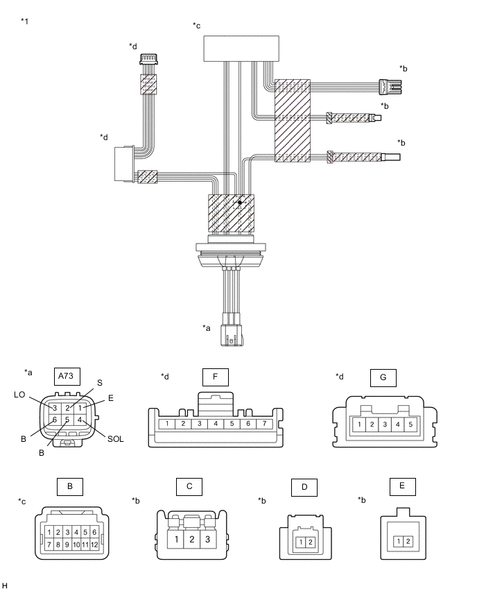
*1 Headlight Unit Assembly RH (Headlight Cord) - - *a Component without harness connected
(to Wire Harness)
*b Component without harness connected
(to Headlight LED Unit Assembly RH)
*c Component without harness connected
(to Light Control ECU)
*d Component without harness connected
(to No. 1 Headlight Clearance LED Unit RH)
-
Measure the resistance according to the value(s) in the table below.
-
Inspect the Lo/Hi beam circuit.
Standard Resistance Tester Connection Condition Specified Condition A73-1 (E) - B-6 Always Below 1 Ω A73-2 (S) - B-12 Always Below 1 Ω A73-3 (LO) - B-7 Always Below 1 Ω B-4 - D-1 Always Below 1 Ω B-10 - D-2 Always Below 1 Ω If the result is not as specified, replace the headlight unit assembly RH (headlight cord).
-
Inspect the Lo/Hi beam shade circuit.
Standard Resistance Tester Connection Condition Specified Condition A73-1 (E) - E-2 Always Below 1 Ω A73-4 (SOL) - E-1 Always Below 1 Ω If the result is not as specified, replace the headlight unit assembly RH (headlight cord).
-
Inspect the headlight fan circuit.
Standard Resistance Tester Connection Condition Specified Condition B-2 - C-3 Always Below 1 Ω B-9 - C-2 Always Below 1 Ω B-11 - C-1 Always Below 1 Ω If the result is not as specified, replace the headlight unit assembly RH (headlight cord).
-
Inspect the clearance light/daytime running light input circuit.
Standard Resistance Tester Connection Condition Specified Condition A73-1 (E) - F-3 Always Below 1 Ω A73-5 (B) - F-2 Always Below 1 Ω A73-6 (B) - F-1 Always Below 1 Ω If the result is not as specified, replace the headlight unit assembly RH (headlight cord).
-
Inspect the clearance light/daytime running light output circuit.
Standard Resistance Tester Connection Condition Specified Condition F-4 - G-5 Always Below 1 Ω F-5 - G-4 Always Below 1 Ω F-6 - G-3 Always Below 1 Ω F-7 - G-1 Always Below 1 Ω If the result is not as specified, replace the headlight unit assembly RH (headlight cord).
-
-
-
INSPECT HEADLIGHT LED UNIT ASSEMBLY RH (w/o Automatic Headlight Beam Level Control System)
-
*a Component without harness connected
(Headlight LED Unit Assembly RH)
Apply battery voltage to the headlight LED unit assembly RH and check that the Lo/Hi beam shade operates.
OK Condition Specified Condition Battery positive (+) → Terminal 1
Battery negative (-) → Terminal 2
Operates normally If the result is not as specified, replace the headlight LED unit assembly RH.
-
-
INSPECT NO. 1 HEADLIGHT CLEARANCE LED UNIT RH (w/o Automatic Headlight Beam Level Control System)
*a Component without harness connected
(No. 1 Headlight Clearance LED Unit RH)
-
Apply battery voltage to the No. 1 headlight clearance LED unit RH and check that the light illuminates.
OK Condition Specified Condition Battery positive (+) → Terminal 1
Battery negative (-) → Terminal 3
Clearance light/daytime running light illuminates If the result is not as specified, replace the No. 1 headlight clearance LED unit RH.
-