LIGHTING SYSTEM(w/ Automatic Headlight Beam Level Control System), Diagnostic DTC:B243D, B243E
| DTC Code | DTC Name |
|---|---|
| B243D | Left Low Beam Fan Malfunction |
| B243E | Right Low Beam Fan Malfunction |
DESCRIPTION
The headlight ECU sub-assembly operates the low beam fan to cool the headlight LED unit in order to prevent the headlight LED unit from overheating.
Illuminates the low beam headlights and continuously operates the low beam fan.
The headlight ECU sub-assembly monitors the pulse signals from the FANP terminal when the low beam fans are operating.
Tech Tips
If B243D or B243E is output, the headlight ECU sub-assembly performs low beam headlight dimming control.
| DTC No. | Detection Item | DTC Detection Condition | Trouble Area | DTC Output from |
|---|---|---|---|---|
| B243D | Left Low Beam Fan Malfunction |
Detection condition:
Malfunction status:
Malfunction duration: |
|
Headlight ECU sub-assembly LH |
| B243E | Right Low Beam Fan Malfunction |
Detection condition:
Malfunction status:
Malfunction duration: |
|
Headlight ECU sub-assembly RH |
-
*1: for Bulb Type Turn Signal Light
-
*2: for LED Type Turn Signal Light
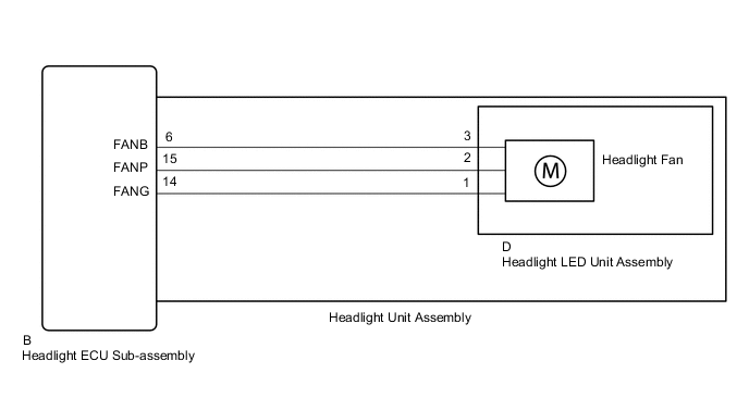
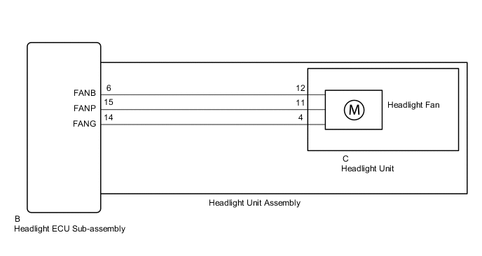
WIRING DIAGRAM
-
for Bulb Type Turn Signal Light
-
for LED Type Turn Signal Light
CAUTION / NOTICE / HINT
Note
If the headlight ECU sub-assembly LH has been replaced, it is necessary to synchronize the vehicle information and initialize the headlight ECU sub-assembly LH.
PROCEDURE
-
CLEAR DTC
-
Connect the GTS to the DLC3.
-
Turn the ignition switch to ON.
-
Turn the GTS on.
-
Enter the following menus: Body Electrical / HL AutoLeveling or HL AutoLeveling (Sub) / Trouble Codes.
-
Clear the DTCs.
Body Electrical > HL AutoLeveling > Clear DTCs
Body Electrical > HL AutoLeveling (Sub) > Clear DTCsResult Proceed to NEXT
NEXT 
-
-
CHECK FOR DTC
-
Connect the GTS to the DLC3.
-
Turn the ignition switch to ON.
-
Operate the light control switch to turn on the low beam headlights and wait 4*1 or 120*2 seconds or more.
-
*1: for Bulb Type Turn Signal Light
-
*2: for LED Type Turn Signal Light
-
-
Turn the GTS on.
-
Enter the following menus: Body Electrical / HL AutoLeveling or HL AutoLeveling (Sub) / Trouble Codes.
-
Check for DTCs.
Body Electrical > HL AutoLeveling > Trouble Codes
Body Electrical > HL AutoLeveling (Sub) > Trouble CodesOK DTC B243D and B243E are not output. Result Result Proceed to OK A NG (DTC B243D is output) B NG (DTC B243E is output) C
A 
USE SIMULATION METHOD TO CHECK Click here
C 
CONFIRM MODEL Click here
B
-
-
CONFIRM MODEL
-
Choose the model to be inspected.
Result Result Proceed to for Bulb Type Turn Signal Light A for LED Type Turn Signal Light B
B
INSPECT HEADLIGHT UNIT ASSEMBLY LH Click here
A
-
-
INSPECT HEADLIGHT UNIT ASSEMBLY LH
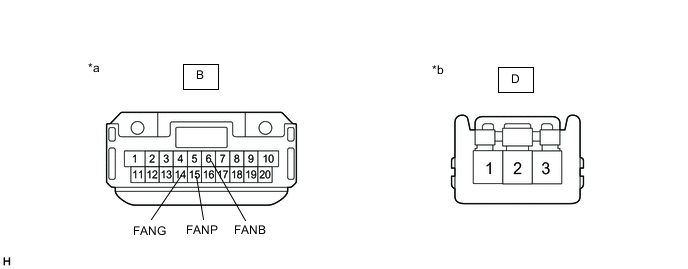
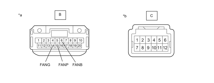
*a Component without harness connected
(to Headlight ECU Sub-assembly LH)
*b Component without harness connected
(to Headlight LED Unit Assembly LH)
-
Remove the headlight assembly LH.
-
Remove the headlight LED unit assembly LH.
-
Measure the resistance according to the value(s) in the table below.
Standard Resistance Tester Connection Condition Specified Condition B-6 (FANB) - D-3 Always Below 1 Ω B-15 (FANP) - D-2 Always Below 1 Ω B-14 (FANG) - D-1 Always Below 1 Ω Result Proceed to OK NG
NG
REPLACE HEADLIGHT UNIT ASSEMBLY LH Click here
OK
-
-
INSPECT HEADLIGHT ECU SUB-ASSEMBLY LH
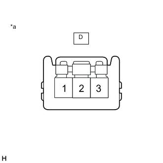
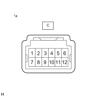
*a Component without harness connected
(to Headlight LED Unit Assembly LH)
-
Connect the B headlight ECU sub-assembly LH connector.
-
Measure the voltage according to the value(s) in the table below.
Standard Voltage Tester Connection Condition Specified Condition D-3 - D-1 Low beam headlights on 4.75 to 5.25 V D-2 - D-1 Low beam headlights on 4.75 to 5.25 V Result Proceed to OK NG
OK
REPLACE HEADLIGHT LED UNIT ASSEMBLY LH Click here
NG
REPLACE HEADLIGHT ECU SUB-ASSEMBLY LH Click here
-
-
INSPECT HEADLIGHT UNIT ASSEMBLY LH
*a Component without harness connected
(to Headlight ECU Sub-assembly LH)
*b Component without harness connected
(to Headlight Unit LH)
-
Remove the headlight assembly LH.
-
Remove the headlight unit LH.
-
Measure the resistance according to the value(s) in the table below.
Standard Resistance Tester Connection Condition Specified Condition B-6 (FANB) - C-12 Always Below 1 Ω B-15 (FANP) - C-11 Always Below 1 Ω B-14 (FANG) - C-4 Always Below 1 Ω Result Proceed to OK NG
NG
REPLACE HEADLIGHT UNIT ASSEMBLY LH Click here
OK
-
-
INSPECT HEADLIGHT ECU SUB-ASSEMBLY LH
*a Component without harness connected
(to Headlight Unit LH)
-
Connect the B headlight ECU sub-assembly LH connector.
-
Measure the voltage according to the value(s) in the table below.
Standard Voltage Tester Connection Condition Specified Condition C-12 - C-4 Low beam headlights on 4.75 to 5.25 V C-11 - C-4 Low beam headlights on 4.75 to 5.25 V Result Proceed to OK NG
OK
REPLACE HEADLIGHT UNIT LH Click here
NG
REPLACE HEADLIGHT ECU SUB-ASSEMBLY LH Click here
-
-
CONFIRM MODEL
-
Choose the model to be inspected.
Result Result Proceed to for Bulb Type Turn Signal Light A for LED Type Turn Signal Light B
B
INSPECT HEADLIGHT UNIT ASSEMBLY RH Click here
A
-
-
INSPECT HEADLIGHT UNIT ASSEMBLY RH
*a Component without harness connected
(to Headlight ECU Sub-assembly RH)
*b Component without harness connected
(to Headlight LED Unit Assembly RH)
-
Remove the headlight assembly RH.
-
Remove the headlight LED unit assembly RH.
-
Measure the resistance according to the value(s) in the table below.
Standard Resistance Tester Connection Condition Specified Condition B-6 (FANB) - D-3 Always Below 1 Ω B-15 (FANP) - D-2 Always Below 1 Ω B-14 (FANG) - D-1 Always Below 1 Ω Result Proceed to OK NG
NG
REPLACE HEADLIGHT UNIT ASSEMBLY RH Click here
OK
-
-
INSPECT HEADLIGHT ECU SUB-ASSEMBLY RH
*a Component without harness connected
(to Headlight LED Unit Assembly RH)
-
Connect the B headlight ECU sub-assembly RH connector.
-
Measure the voltage according to the value(s) in the table below.
Standard Voltage Tester Connection Condition Specified Condition D-3 - D-1 Low beam headlights on 4.75 to 5.25 V D-2 - D-1 Low beam headlights on 4.75 to 5.25 V Result Proceed to OK NG
OK
REPLACE HEADLIGHT LED UNIT ASSEMBLY RH Click here
NG
REPLACE HEADLIGHT ECU SUB-ASSEMBLY RH Click here
-
-
INSPECT HEADLIGHT UNIT ASSEMBLY RH
*a Component without harness connected
(to Headlight ECU Sub-assembly RH)
*b Component without harness connected
(to Headlight Unit RH)
-
Remove the headlight assembly RH.
-
Remove the headlight unit RH.
-
Measure the resistance according to the value(s) in the table below.
Standard Resistance Tester Connection Condition Specified Condition B-6 (FANB) - C-12 Always Below 1 Ω B-15 (FANP) - C-11 Always Below 1 Ω B-14 (FANG) - C-4 Always Below 1 Ω Result Proceed to OK NG
NG
REPLACE HEADLIGHT UNIT ASSEMBLY RH Click here
OK
-
-
INSPECT HEADLIGHT ECU SUB-ASSEMBLY RH
*a Component without harness connected
(to Headlight Unit RH)
-
Connect the B headlight ECU sub-assembly RH connector.
-
Measure the voltage according to the value(s) in the table below.
Standard Voltage Tester Connection Condition Specified Condition C-12 - C-4 Low beam headlights on 4.75 to 5.25 V C-11 - C-4 Low beam headlights on 4.75 to 5.25 V Result Proceed to OK NG
OK
REPLACE HEADLIGHT UNIT RH Click here
NG
REPLACE HEADLIGHT ECU SUB-ASSEMBLY RH Click here
-