Click here
-

CHECK WINDSHIELD WIPER MOTOR ASSEMBLY
-
Disconnect the A31 windshield wiper motor assembly connector.
-
Measure the voltage and resistance on the wire harness side connector according to the value(s) in the table below.
Table 1. for LHD Terminal No.
(Symbol)
Wiring Color Terminal Description Condition Specified Condition A31-4 (+B) - Body ground SB - Body ground Ignition switch ON signal (Power source circuit) Ignition switch ON 11 to 14 V Less than approximately 60 seconds after ignition switch turned off Approximately 60 seconds after ignition switch turned off Below 1 V A31-1 (GND) - Body ground W-B - Body ground Ground Always Below 1 Ω Table 2. for RHD Terminal No.
(Symbol)
Wiring Color Terminal Description Condition Specified Condition A31-1 (+B) - Body ground SB - Body ground Ignition switch ON signal (Power source circuit) Ignition switch ON 11 to 14 V Less than approximately 60 seconds after ignition switch turned off Approximately 60 seconds after ignition switch turned off Below 1 V A31-4 (GND) - Body ground W-B - Body ground Ground Always Below 1 Ω -
Connect the A31 windshield wiper motor assembly connector.
Tip:Since the A31 windshield wiper motor assembly connector is a waterproof type connector, the voltage and pulses cannot be checked directly. The values listed are for reference only.
-
Measure the voltage and check for pulses according to the value(s) in the table below.
Table 3. for LHD Terminal No.
(Symbol)
Wiring Color Terminal Description Condition Specified Condition A31-3 (2S) - Body ground B - Body ground Windshield wiper motor assembly HI operation signal Windshield wiper motor assembly stopped 11 to 14 V Windshield wiper motor assembly operating in HI Below 1 V A31-2 (LIN) - Body ground R - Body ground LIN communication signal Ignition switch ON Pulse generation Table 4. for RHD Terminal No.
(Symbol)
Wiring Color Terminal Description Condition Specified Condition A31-2 (2S) - Body ground B - Body ground Windshield wiper motor assembly HI operation signal Windshield wiper motor assembly stopped 11 to 14 V Windshield wiper motor assembly operating in HI Below 1 V A31-3 (LIN) - Body ground R - Body ground LIN communication signal Ignition switch ON Pulse generation
-
-
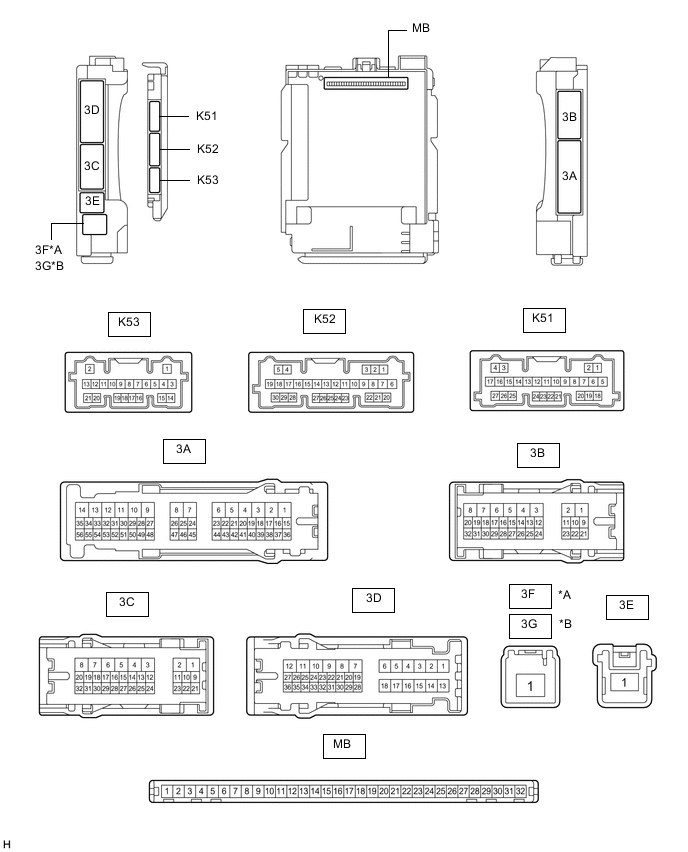
*A for LHD *B for RHD CHECK MAIN BODY ECU (MULTIPLEX NETWORK BODY ECU) AND INSTRUMENT PANEL JUNCTION BLOCK ASSEMBLY
-
Disconnect the instrument panel junction block assembly and main body ECU (multiplex network body ECU) connectors.
-
Measure the voltage and resistance according to the value(s) in the table below.
Terminal No. (Symbol) Wiring Color Terminal Description Condition Specified Condition 3B-3 - Body ground LA - Body ground Ground Always Below 1 Ω 3B-23 - Body ground*1 BE - Body ground Battery power supply Always 11 to 14 V 3C-1 - Body ground*2 LG - Body ground Battery power supply Always 11 to 14 V 3F-1 - Body ground*3 W - Body ground Battery power supply Always 11 to 14 V 3G-1 - Body ground*4 W - Body ground Battery power supply Always 11 to 14 V
-
*1: w/ Door Control Battery
-
*2: w/o Door Control Battery
-
*3: for LHD
-
*4: for RHD
-
-
Connect the instrument panel junction block assembly and main body ECU (multiplex network body ECU) connectors.
-
Measure the voltage and check for pulses according to the value(s) in the table below.
Terminal No. (Symbol) Wiring Color Terminal Description Condition Specified Condition 3C-2 - Body ground R - Body ground Washer circuit IG power source Ignition switch ON 11 to 14 V K51-3 (LIN3) - Body ground R - Body ground LIN communication line Ignition switch ON Pulse generation K51-12 (FWSR) - Body ground L - Body ground WASHER Relay operation signal Ignition switch ON, front washer switch off 11 to 14 V Ignition switch ON, front washer switch on Below 2 V K52-21 (WPS) - Body ground LG - Body ground WIPER Relay operation signal Ignition switch ON 11 to 14 V Less than approximately 60 seconds after ignition switch turned off Approximately 60 seconds after ignition switch turned off Below 1 V
-
-

*A for LHD *B for RHD CHECK RAIN SENSOR (w/ Auto Wiper System)
-
Disconnect the V4*1 or V5*2 rain sensor connector.
-
*1: for LHD
-
*2: for RHD
-
-
Measure the voltage and resistance and check for pulses according to the value(s) in the table below.
Table 5. for LHD Terminal No. (Symbol) Wiring Color Terminal Description Condition Specified Condition V4-2 (ES) - Body ground W-B - Body ground Ground Always Below 1 Ω V4-3 (MPX) - Body ground GR - Body ground LIN communication signal Ignition switch ON Pulse generation V4-4 (SIG) - Body ground B - Body ground IG power source circuit Ignition switch off Below 1 V Ignition switch ON 11 to 14 V Table 6. for RHD Terminal No. (Symbol) Wiring Color Terminal Description Condition Specified Condition V5-2 (ES) - Body ground W-B - Body ground Ground Always Below 1 Ω V5-3 (MPX) - Body ground GR - Body ground LIN communication signal Ignition switch ON Pulse generation V5-4 (SIG) - Body ground B - Body ground IG power source circuit Ignition switch off Below 1 V Ignition switch ON 11 to 14 V
-
-

CHECK HEADLIGHT CLEANER CONTROL RELAY (w/ Headlight Cleaner System)
-
Disconnect the A9 headlight cleaner control relay connector.
-
Measure the voltage and resistance on the wire harness side connector according to the value(s) in the table below.
Terminal No. (Symbol) Wiring Color Terminal Description Condition Specified Condition A9-3 (IG) - Body ground B - Body ground IG power source circuit Ignition switch off Below 1 V Ignition switch ON 11 to 14 V A9-4 (E) - Body ground W-B - Body ground Ground Always Below 1 Ω A9-6 (PB) - Body ground R - Body ground Headlight cleaner motor operation signal Always 11 to 14 V
-
-
CHECK HEADLIGHT ECU SUB-ASSEMBLY RH (w/ Headlight Cleaner System)
for Bulb Type Turn Signal Light:Click here
for LED Type Turn Signal Light:Click here
-
CHECK COMBINATION METER ASSEMBLY