WIPER AND WASHER SYSTEM Headlight Cleaner Motor and Relay Circuit
DESCRIPTION
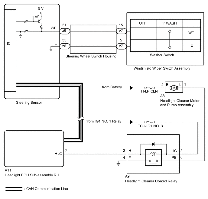
The headlight ECU sub-assembly RH controls the headlight cleaner motor and pump assembly.
WIRING DIAGRAM
-
for LHD
-
for RHD

CAUTION / NOTICE / HINT
Note
-
Check that the front washers are normal before performing the following procedure.
-
Check that the lighting system is normal before performing the following procedure.
-
Inspect the fuses and relays for circuits related to this system before performing the following procedure.
PROCEDURE
-
PERFORM ACTIVE TEST USING GTS
-
Connect the GTS to the DLC3.
-
Turn the ignition switch to ON.
-
Turn the GTS on.
-
Enter following menus: Body Electrical / HL AutoLeveling (Sub) / Active Test.
-
Perform the Active Test according to the display on the GTS.
Body Electrical > HL AutoLeveling (Sub) > Active TestTester Display Measurement Item Control Range Diagnostic Note Headlight Cleaner Function to operate the headlight cleaner motor and pump assembly OFF or ON -
Body Electrical > HL AutoLeveling (Sub) > Active TestTester Display Headlight Cleaner OK Headlight cleaner motor and pump assembly is normal. Result Proceed to OK NG
NG 
INSPECT HEADLIGHT CLEANER MOTOR AND PUMP ASSEMBLY Click here
OK 
-
-
READ VALUE USING GTS
-
Connect the GTS to the DLC3.
-
Turn the ignition switch to ON.
-
Turn the GTS on.
-
Enter the following menus: Body Electrical / HL AutoLeveling (Sub) / Data List.
-
Read the Data List according to the display on the GTS.
Body Electrical > HL AutoLeveling (Sub) > Data ListTester Display Measurement Item Range Normal Condition Diagnostic Note Front Window Washer Switch Windshield wiper switch assembly (washer switch) condition OFF or ON OFF: Windshield wiper switch assembly (washer switch) off
ON: Windshield wiper switch assembly (washer switch) on
-
Body Electrical > HL AutoLeveling (Sub) > Data ListTester Display Front Window Washer Switch OK The GTS display is normal. Result Proceed to OK NG
OK 
REPLACE NO. 1 HEADLIGHT ECU SUB-ASSEMBLY RH Click here
NG
REPLACE STEERING SENSOR Click here
-
-
INSPECT HEADLIGHT CLEANER MOTOR AND PUMP ASSEMBLY
-
Remove the headlight cleaner motor and pump assembly.
-
Inspect the headlight cleaner motor and pump assembly.
Result Proceed to OK NG
NG
REPLACE HEADLIGHT CLEANER MOTOR AND PUMP ASSEMBLY Click here
OK
-
-
INSPECT HEADLIGHT CLEANER CONTROL RELAY
-
Remove the headlight cleaner control relay.
-
Inspect the headlight cleaner control relay.
Result Proceed to OK NG
NG
REPLACE HEADLIGHT CLEANER CONTROL RELAY Click here
OK
-
-
CHECK HARNESS AND CONNECTOR (POWER SOURCE - HEADLIGHT CLEANER MOTOR AND PUMP ASSEMBLY)
-
Disconnect the A8 headlight cleaner motor and pump assembly connector.
-
Measure the voltage according to the value(s) in the table below.
Standard Voltage Tester Connection Condition Specified Condition A8-2 (B) - Body ground Always 11 to 14 V Result Proceed to OK NG
NG
REPAIR OR REPLACE HARNESS OR CONNECTOR
OK
-
-
CHECK HARNESS AND CONNECTOR (HEADLIGHT CLEANER MOTOR AND PUMP ASSEMBLY - HEADLIGHT CLEANER CONTROL RELAY)
-
Disconnect the A9 headlight cleaner control relay connector.
-
Measure the resistance according to the value(s) in the table below.
Standard Resistance Tester Connection Condition Specified Condition A8-1 (L) - A9-6 (PB) Always Below 1 Ω Result Proceed to OK NG
NG
REPAIR OR REPLACE HARNESS OR CONNECTOR
OK
-
-
CHECK HARNESS AND CONNECTOR (POWER SOURCE - HEADLIGHT CLEANER CONTROL RELAY)
-
Measure the voltage according to the value(s) in the table below.
Standard Voltage Tester Connection Condition Specified Condition A9-3 (IG) - Body ground Ignition switch ON 11 to 14 V Ignition switch off Below 1 V Result Proceed to OK NG
NG
REPAIR OR REPLACE HARNESS OR CONNECTOR
OK
-
-
CHECK HARNESS AND CONNECTOR (HEADLIGHT CLEANER CONTROL RELAY - BODY GROUND)
-
Measure the resistance according to the value(s) in the table below.
Standard Resistance Tester Connection Condition Specified Condition A9-4 (E) - Body ground Always Below 1 Ω Result Proceed to OK NG
NG
REPAIR OR REPLACE HARNESS OR CONNECTOR
OK
-
-
CHECK HARNESS AND CONNECTOR (HEADLIGHT ECU SUB-ASSEMBLY RH - HEADLIGHT CLEANER CONTROL RELAY)
-
Disconnect the A11 headlight ECU sub-assembly RH connector.
-
Measure the resistance according to the value(s) in the table below.
Standard Resistance Tester Connection Condition Specified Condition A11-7 (HLC) - A9-2 (H) Always Below 1 Ω Result Proceed to OK NG
OK
REPLACE HEADLIGHT ECU SUB-ASSEMBLY RH Click here
NG
REPAIR OR REPLACE HARNESS OR CONNECTOR
-