FRONT DOOR DISASSEMBLY

CAUTION / NOTICE / HINT
The necessary procedures (adjustment, calibration, initialization, or registration) that must be performed after parts are removed and installed, or replaced during front door removal/installation are shown below.
| Replaced Part or Performed Procedure | Necessary Procedure | Effect/Inoperative Function when Necessary Procedure not Performed | Link |
|---|---|---|---|
| Disconnect cable from negative battery terminal | Perform steering sensor zero point calibration | Lane departure alert system (w/ Steering Control) | |
| Pre-collision system | |||
| Memorize steering angle neutral point | Parking assist monitor system | ||
|
Initialize power window control system |
|
Tech Tips
-
Use the same procedure for the RH side and LH side.
-
The following procedure is for the LH side.
PROCEDURE
-
PRECAUTION
Note
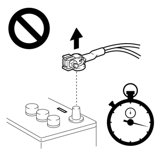
After turning the ignition switch off, waiting time may be required before disconnecting the cable from the negative (-) battery terminal. Therefore, make sure to read the disconnecting the cable from the negative (-) battery terminal notices before proceeding with work.
-
DISCONNECT CABLE FROM NEGATIVE BATTERY TERMINAL
for 2AR-FE:
for A25A-FKS:
for 2GR-FKS:
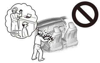
CAUTION:
Wait at least 90 seconds after disconnecting the cable from the negative (-) battery terminal to disable the SRS system.
-
REMOVE FRONT DOOR LOWER FRAME BRACKET GARNISH
-
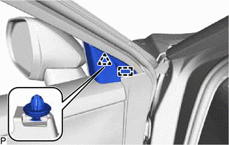
Disengage the clip and guide to remove the front door lower frame bracket garnish.
-
-
REMOVE FRONT DOOR ARMREST COVER SUB-ASSEMBLY
-
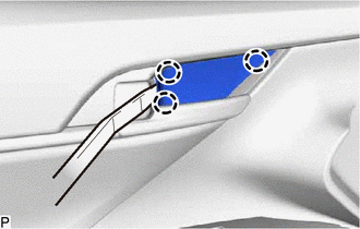
Using a moulding remover, disengage the 3 claws to remove the front door armrest cover sub-assembly.
-
-
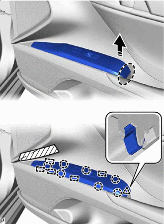
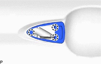
REMOVE MULTIPLEX NETWORK MASTER SWITCH ASSEMBLY WITH FRONT DOOR UPPER ARMREST BASE PANEL (for Driver Side)
-

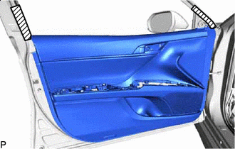
Protective Tape Apply protective tape to the front door trim board sub-assembly as shown in the illustration.
-

Place Hand Here 
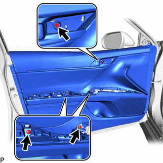
Remove in this Direction Disengage the clip, 7 claws and 5 guides as shown in the illustration.
-
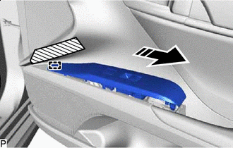
Remove in this Direction Disengage the guide as shown in the illustration.
-
Disconnect the connector to remove the multiplex network master switch assembly with front door upper armrest base panel.
-
-
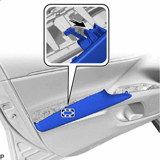
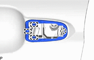
REMOVE POWER WINDOW REGULATOR SWITCH ASSEMBLY WITH FRONT DOOR UPPER ARMREST BASE PANEL (for Front Passenger Side)
-
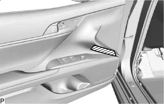
Protective Tape Apply protective tape to the front door trim board sub-assembly as shown in the illustration.
-
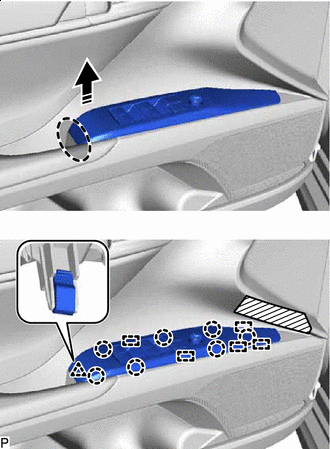
Place Hand Here Remove in this Direction Disengage the clip, 7 claws and 5 guides as shown in the illustration.
-
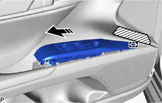
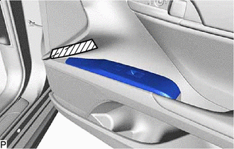
Remove in this Direction Disengage the guide as shown in the illustration.
-
Disconnect the connector to remove the power window regulator switch assembly with front door upper armrest base panel.
-
-
REMOVE FRONT ARMREST ASSEMBLY
-
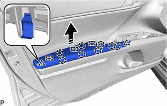
Remove in this Direction Disengage the 3 clips, 8 claws and 3 guides as shown in the illustration.
-
Remove in this Direction Disengage the guide to remove the front armrest assembly as shown in the illustration.
-
-
REMOVE COURTESY LIGHT ASSEMBLY
-
REMOVE FRONT DOOR TRIM BOARD SUB-ASSEMBLY
-
Protective Tape Apply protective tape to the front door panel as shown in the illustration.
-
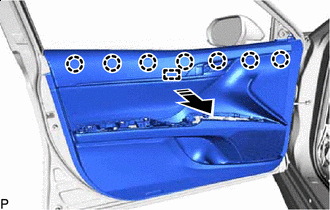
Remove the 3 screws.
-
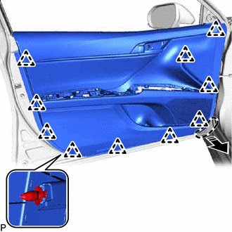
Place Hand Here Remove in this Direction Disengage the 10 clips as shown in the illustration.
-
Remove in this Direction Disengage the 7 claws and guide as shown in the illustration.
-
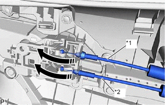
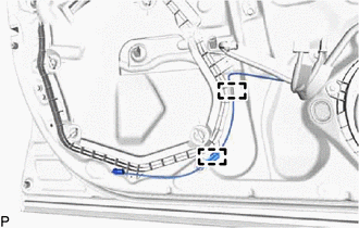
*1 Front Door Inside Locking Cable Assembly *2 Front Door Lock Remote Control Cable Assembly Remove in this Direction Disconnect the front door lock remote control cable assembly and front door inside locking cable assembly to remove the front door trim board sub-assembly as shown in the illustration.
-
-
REMOVE FRONT DOOR INNER GLASS WEATHERSTRIP WITH FRONT DOOR VENT SEAL
-
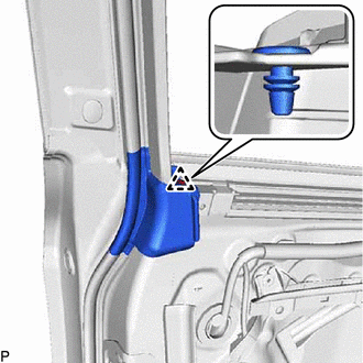
Disengage the clip.
-
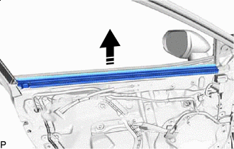
Remove in this Direction Remove the front door inner glass weatherstrip with front door vent seal as shown in the illustration.
-
-
REMOVE FRONT DOOR VENT SEAL
-
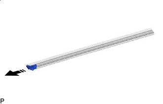
Remove in this Direction Remove the front door vent seal from the front door inner glass weatherstrip as shown in the illustration.
-
-
REMOVE FRONT DOOR INSIDE HANDLE SUB-ASSEMBLY
-
Disengage the 3 claws to remove the front door inside handle sub-assembly.
-
-
REMOVE OUTER MIRROR CONTROL ECU ASSEMBLY
-
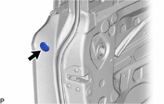
REMOVE HOLE PLUG
-
REMOVE OUTER MIRROR INSTALL HOLE COVER
-
REMOVE OUTER REAR VIEW MIRROR ASSEMBLY WITH COVER
-
REMOVE FRONT NO. 1 SPEAKER ASSEMBLY
-
REMOVE FRONT DOOR SERVICE HOLE COVER
-
Disengage the 2 clamps.
-
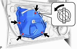
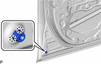
Turn each front door weatherstrip clip 45 degrees and remove the 4 front door weatherstrip clips as shown in the illustration.
-
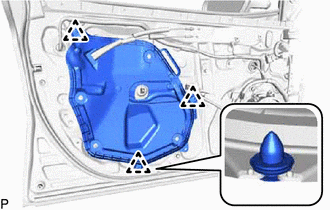
Disengage the 3 clips to remove the front door service hole cover.
-
-
REMOVE DOOR SIDE AIRBAG SENSOR
-
REMOVE FRONT DOOR GLASS SUB-ASSEMBLY
-
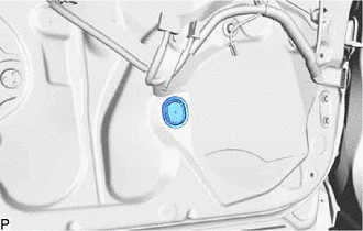
Remove the hole plug.
-
for Driver Side:
-
Connect the multiplex network master switch assembly.
-
-
for Front Passenger Side:
-
Connect the power window regulator switch assembly.
-
-
Connect the cable to the negative (-) battery terminal.
-
Turn the ignition switch to ON.
-
Move the front door glass sub-assembly so that the door glass bolts can be seen.
-
Turn the ignition switch off.
-
Disconnect the cable from the negative (-) battery terminal.
-
for Driver Side:
-
Disconnect the multiplex network master switch assembly.
-
-
for Front Passenger Side:
-
Disconnect the power window regulator switch assembly.
-
-
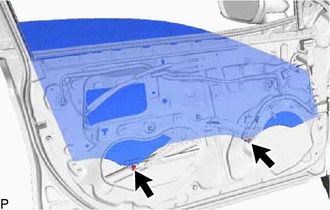
Remove the 2 bolts.
Note
After the bolts are removed, do not allow the front door glass sub-assembly to fall.
-
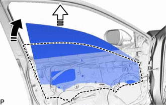
Remove in this Direction (1) 
Remove in this Direction (2) Remove the front door glass sub-assembly as indicated by the arrows, in the order shown in the illustration.
Note
Do not damage the front door glass sub-assembly.
-
-
REMOVE FRONT DOOR WINDOW REGULATOR ASSEMBLY
-
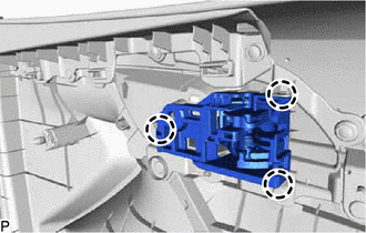
Disengage the 2 claws to remove the front door No. 2 service hole cover.
-
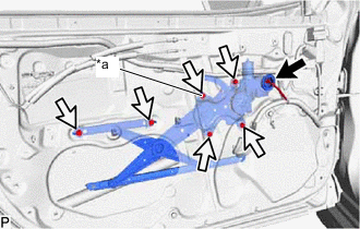
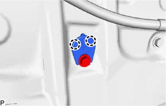
*a Temporary Bolt Disconnect the connector.
-
Loosen the temporary bolt.
Note
Do not remove the temporary bolt. If the temporary bolt is removed, the front door window regulator assembly may fall and cause damage.
-
Remove the 5 bolts.
-
Remove the front door window regulator assembly.
-
Remove the temporary bolt from the front door window regulator assembly.
-
-
REMOVE FRONT DOOR PANEL PROTECTOR
-
Remove the front door panel protector.
-
-
REMOVE FRONT DOOR GLASS RUN
-
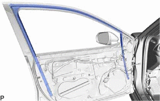
Remove the front door glass run.
-
-
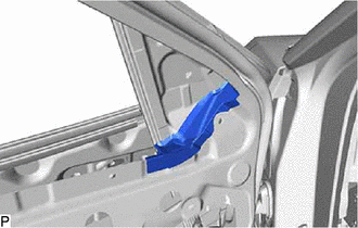
REMOVE FRONT DOOR REAR LOWER FRAME SUB-ASSEMBLY
-
Remove in this Direction Remove the 2 bolts.
-
Disengage the guide and remove the front door rear lower frame sub-assembly as shown in the illustration.
-
-
REMOVE FRONT DOOR OUTSIDE HANDLE ASSEMBLY
-
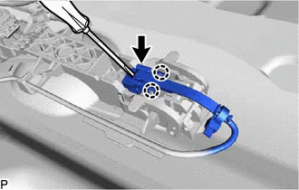
Disengage the 2 claws.
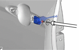
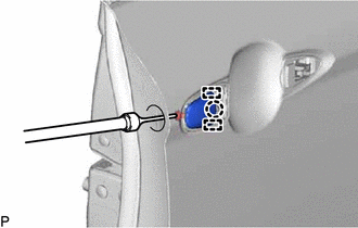
-
Using a screwdriver, disconnect the connector.
-
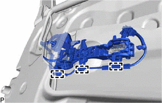
Disengage the 3 clamps.
-
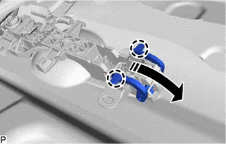
Disengage in this Direction Disengage the 2 claws and move the lever as shown in the illustration.
-
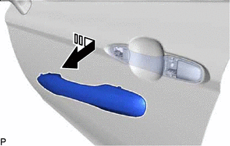
Remove in this Direction Remove the front door outside handle assembly as shown in the illustration.
-
-
REMOVE FRONT DOOR LOCK CYLINDER ASSEMBLY (for Driver Side)
-
Remove the hole plug.
-
Using a T30 "TORX" socket wrench, loosen the screw and remove the front door lock cylinder assembly.
-
-
REMOVE FRONT DOOR OUTSIDE HANDLE COVER (for Front Passenger Side)
-
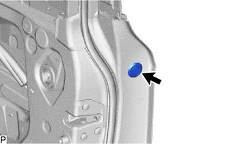
Remove the hole plug.
-
Using a T30 "TORX" socket wrench, loosen the screw.
-
Disengage the 2 guides and claw and remove the front door outside handle cover.
-
-
REMOVE FRONT DOOR FRONT OUTSIDE HANDLE PAD
-
Disengage the 3 claws to remove the front door front outside handle pad.
-
-
REMOVE FRONT DOOR REAR OUTSIDE HANDLE PAD
-
Disengage the 3 guides and claw to remove the front door rear outside handle pad.
-
-
REMOVE FRONT DOOR LOCK WITH MOTOR ASSEMBLY
-
REMOVE FRONT DOOR OUTSIDE HANDLE FRAME SUB-ASSEMBLY
-
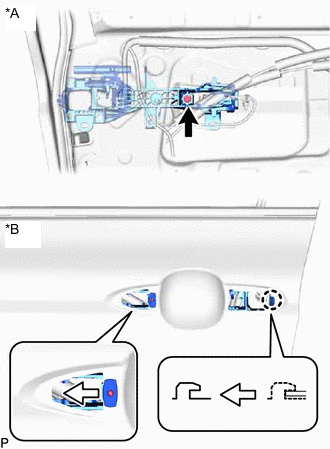
*A Inside *B Outside Using a T30 "TORX" socket wrench, remove the screw.
-
Slide the front door outside handle frame sub-assembly as shown in the illustration to disengage the claw and then remove the front door outside handle frame sub-assembly.
-
-
REMOVE FRONT DOOR LOCK OPEN ROD
-
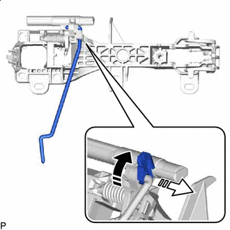
Remove in this Direction (1) Remove in this Direction (2) Remove the front door lock open rod as indicated by the arrows, in the order shown in the illustration.
-
-
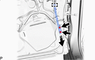
REMOVE FRONT DOOR CHECK ASSEMBLY
-
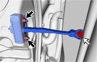

Nut 
Bolt Remove the 2 nuts, bolt and front door check assembly.
-
-
REMOVE FRONT DOOR WEATHERSTRIP
-
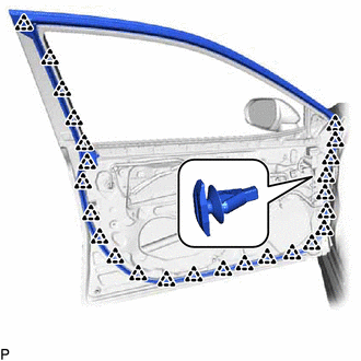
Using a clip remover, disengage the 25 clips and remove the front door weatherstrip.
-
-
REMOVE DOOR FRAME GARNISH
-
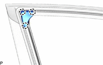
Disengage the 3 claws to remove the door frame garnish.
-
-
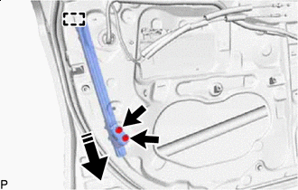
REMOVE FRONT DOOR FRONT LOWER FRAME SUB-ASSEMBLY
-
Remove in this Direction Remove the 2 bolts.
-
Disengage the guide and remove the front door front lower frame sub-assembly as shown in the illustration.
-
-
REMOVE FRONT DOOR PANEL CUSHION
-
Disengage the 2 claws to remove the front door panel cushion.
-
-
REMOVE FRONT DOOR NO. 2 WEATHERSTRIP
-
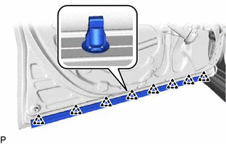
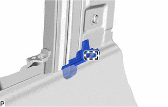
Disengage the 8 clips to remove the front door No. 2 weatherstrip.
-
-
REMOVE FRONT DOOR BELT MOULDING ASSEMBLY
-
REMOVE FRONT DOOR FRONT LOWER FRAME UPPER COVER
-
REMOVE DOOR WINDOW FRAME MOULDING CLIP
-
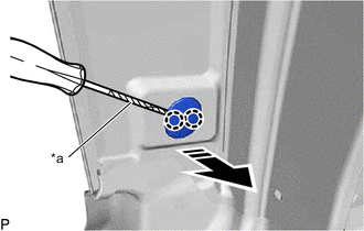
*a Protective Tape Remove in this Direction Using a screwdriver with its tip wrapped with protective tape, disengage the 2 claws to remove the door window frame moulding clip.
-
-
REMOVE FRONT DOOR REAR WINDOW FRAME MOULDING
-
REMOVE FRONT DOOR REAR OUTSIDE SEAL
-
Disengage the guide to remove the front door rear outside seal.
-
-
REMOVE FRONT DOOR UPPER WINDOW FRAME MOULDING
-
REMOVE FRONT DOOR NO. 2 STRIPE
-
REMOVE FRONT DOOR NO. 3 STRIPE