PANORAMIC MOON ROOF SYSTEM Panoramic Moon Roof System does not Operate
DESCRIPTION
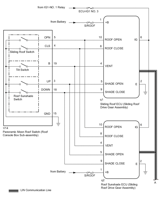
The sliding roof ECU (sliding roof drive gear assembly) and roof sunshade ECU (sliding roof drive gear assembly) receive each other's position information from the main body ECU (multiplex network body ECU) via LIN communication.
The sliding roof ECU (sliding roof drive gear assembly) and roof sunshade ECU (sliding roof drive gear assembly) receive signals from each switch, and operate their built-in motors.
For the linked functions of the sliding roof and roof sunshade refer to Operation Check.
WIRING DIAGRAM
CAUTION / NOTICE / HINT
Note
-
Inspect the fuses for circuits related to this system before performing the following procedure.
-
The sliding roof auto operation function can be customized. Make sure that the function is set to ON.
-
If the sliding roof ECU (sliding roof drive gear assembly) or roof sunshade ECU (sliding roof drive gear assembly) is removed and reinstalled or replaced, the sliding roof ECU (sliding roof drive gear assembly) or roof sunshade ECU (sliding roof drive gear assembly) must be initialized.
-
The panoramic moon roof system uses the CAN and LIN communication systems. First, confirm that there are no malfunctions in the CAN and LIN communication systems. Refer to How to Proceed with Troubleshooting.
-
If a sliding roof ECU (sliding roof drive gear assembly) or roof sunshade ECU (sliding roof drive gear assembly) DTC is output,perform troubleshooting for the DTC first.
PROCEDURE
-
CHECK FOR DTC (MAIN BODY)
-
Clear the DTCs.
Body Electrical > Main Body > Clear DTCs -
Check for DTCs.
Body Electrical > Main Body > Trouble CodesOK DTCs B1273 and B2329 are not output. Result Proceed to OK NG
NG 
GO TO LIN COMMUNICATION SYSTEM (Proceed to How to Proceed with Troubleshooting) Click here
OK 
-
-
CHECK FOR DTC (SLIDING ROOF AND SLIDING SUNSHADE)
-
Clear the DTCs.
Body Electrical > Sliding Roof > Clear DTCs
Body Electrical > Sliding Sunshade > Clear DTCs -
Check for DTCs.
Body Electrical > Sliding Roof > Trouble Codes
Body Electrical > Sliding Sunshade > Trouble CodesOK DTCs B2341 and B2344 are not output. Result Proceed to OK NG
NG
GO TO DIAGNOSTIC TROUBLE CODE CHART Click here
OK
-
-
CHECK POWER WINDOW CONTROL SYSTEM
-
Check the power window control system operates normally.
OK The power window control system operates normally. Result Proceed to OK NG
NG
GO TO POWER WINDOW CONTROL SYSTEM Click here
OK
-
-
PERFORM ACTIVE TEST USING GTS (SLIDING ROOF)
-
Connect the GTS to the DLC3.
-
Turn the ignition switch to ON.
-
Turn the GTS on.
-
Enter the following menus: Body Electrical / Sliding Roof / Active Test.
-
Perform the Active Test according to the display on the GTS.
Body Electrical > Sliding Roof > Active TestTester Display Measurement Item Control Range Diagnostic Note Slide Roof Operate sliding roof motor OFF / Opn/Dwn / Clos/Up -
Body Electrical > Sliding Roof > Active TestTester Display Slide Roof OK Slide roof is operated using GTS. Result Proceed to OK NG
NG 
CHECK HARNESS AND CONNECTOR (ROOF SUNSHADE ECU (SLIDING ROOF DRIVE GEAR ASSEMBLY) - BATTERY AND BODY GROUND) Click here
OK
-
-
READ VALUE USING GTS (SLIDING ROOF)
-
Connect the GTS to the DLC3.
-
Turn the ignition switch to ON.
-
Turn the GTS on.
-
Enter the following menus: Body Electrical / Sliding Roof / Data List.
-
Read the Data List according to the display on the GTS.
Body Electrical > Sliding Roof > Data ListTester Display Measurement Item Range Normal Condition Diagnostic Note Vent Switch Tilt switch signal OFF or ON OFF: Tilt switch not pressed
ON: Tilt switch pressed
- Roof Open Switch Sliding roof open switch signal OFF or ON OFF: Sliding roof switch not slid backward
ON: Sliding roof switch slid backward
- Roof Close Switch Sliding roof close switch signal OFF or ON OFF: Sliding roof switch not slid forward
ON: Sliding roof switch slid forward
- Shade Close Switch Roof sunshade close switch signal OFF or ON OFF: Roof sunshade switch not slid forward
ON: Roof sunshade switch slid forward
- Shade Open Switch Roof sunshade open switch signal OFF or ON OFF: Roof sunshade switch not slid backward
ON: Roof sunshade switch slid backward
-
Body Electrical > Sliding Roof > Data ListTester Display Vent Switch Roof Open Switch Roof Close Switch Shade Close Switch Shade Open Switch OK The GTS display changes according to switch operation as shown in the table. Result Proceed to OK NG
NG
INSPECT PANORAMIC MOON ROOF SWITCH (ROOF CONSOLE BOX SUB-ASSEMBLY) Click here
OK
-
-
PERFORM ACTIVE TEST USING GTS (SLIDING SUNSHADE)
-
Connect the GTS to the DLC3.
-
Turn the ignition switch to ON.
-
Turn the GTS on.
-
Enter the following menus: Body Electrical / Sliding Sunshade / Active Test.
-
Perform the Active Test according to the display on the GTS.
Body Electrical > Sliding Sunshade > Active TestTester Display Measurement Item Control Range Diagnostic Note Sliding Sunshade Operate roof sunshade motor OFF / Open / Close -
Body Electrical > Sliding Sunshade > Active TestTester Display Sliding Sunshade OK Roof sunshade is operated using GTS. Result Proceed to OK NG
NG
CHECK HARNESS AND CONNECTOR (SLIDING ROOF ECU (SLIDING ROOF DRIVE GEAR ASSEMBLY) - BATTERY AND BODY GROUND) Click here
OK
-
-
READ VALUE USING GTS (SLIDING SUNSHADE)
-
Connect the GTS to the DLC3.
-
Turn the ignition switch to ON.
-
Turn the GTS on.
-
Enter the following menus: Body Electrical / Sliding Sunshade / Data List.
-
Read the Data List according to the display on the GTS.
Body Electrical > Sliding Sunshade > Data ListTester Display Measurement Item Range Normal Condition Diagnostic Note Vent Switch Tilt switch signal OFF or ON OFF: Tilt switch not pressed
ON: Tilt switch pressed
- Roof Open Switch Sliding roof open switch signal OFF or ON OFF: Sliding roof switch not slid backward
ON: Sliding roof switch slid backward
- Roof Close Switch Sliding roof close switch signal OFF or ON OFF: Sliding roof switch not slid forward
ON: Sliding roof switch slid forward
- Shade Close Switch Roof sunshade close switch signal OFF or ON OFF: Roof sunshade switch not slid forward
ON: Roof sunshade switch slid forward
- Shade Open Switch Roof sunshade open switch signal OFF or ON OFF: Roof sunshade switch not slid backward
ON: Roof sunshade switch slid backward
-
Body Electrical > Sliding Sunshade > Data ListTester Display Vent Switch Roof Open Switch Roof Close Switch Shade Close Switch Shade Open Switch OK The GTS display changes according to switch operation as shown in the table. Result Proceed to OK NG
OK
USE SIMULATION METHOD TO CHECK Click here
NG
-
-
INSPECT PANORAMIC MOON ROOF SWITCH (ROOF CONSOLE BOX SUB-ASSEMBLY)
-
Remove the panoramic moon roof switch (roof console box sub-assembly).
-
Inspect the panoramic moon roof switch (roof console box sub-assembly).
Result Proceed to OK NG
NG
REPLACE PANORAMIC MOON ROOF SWITCH (ROOF CONSOLE BOX SUB-ASSEMBLY) Click here
OK
-
-
CHECK HARNESS AND CONNECTOR (ROOF SUNSHADE ECU (SLIDING ROOF DRIVE GEAR ASSEMBLY) - PANORAMIC MOON ROOF SWITCH (ROOF CONSOLE BOX SUB-ASSEMBLY) AND BODY GROUND)
-
Disconnect the q2 roof sunshade ECU (sliding roof drive gear assembly) connector.
-
Disconnect the q1 sliding roof ECU (sliding roof drive gear assembly) connector.
-
Disconnect the V14 panoramic moon roof switch (roof console box sub-assembly) connector.
-
Measure the resistance according to the value(s) in the table below.
Standard Resistance Tester Connection Condition Specified Condition q2-10 (ROOF OPEN) - V14-5 (OPN) Always Below 1 Ω q2-10 (ROOF OPEN) or V14-5 (OPN) - Body ground Always 10 kΩ or higher q2-8 (ROOF CLOSE) - V14-4 (CLS) Always Below 1 Ω q2-8 (ROOF CLOSE) or V14-4 (CLS) - Body ground Always 10 kΩ or higher q2-4 (VENT) - V14-19 (B) Always Below 1 Ω q2-4 (VENT) or V14-19 (B) - Body ground Always 10 kΩ or higher q2-5 (SHADE OPEN) - V14-3 (UP) Always Below 1 Ω q2-5 (SHADE OPEN) or V14-3 (UP) - Body ground Always 10 kΩ or higher q2-9 (SHADE CLOSE) - V14-18 (DOWN) Always Below 1 Ω q2-9 (SHADE CLOSE) or V14-18 (DOWN) - Body ground Always 10 kΩ or higher q2-2 (E) - Body ground Always Below 1 Ω V14-15 (GND) - Body ground Always Below 1 Ω Result Proceed to OK NG
OK
REPLACE ROOF SUNSHADE ECU (SLIDING ROOF DRIVE GEAR ASSEMBLY) Click here
NG
REPAIR OR REPLACE HARNESS OR CONNECTOR
-
-
CHECK HARNESS AND CONNECTOR (SLIDING ROOF ECU (SLIDING ROOF DRIVE GEAR ASSEMBLY) - BATTERY AND BODY GROUND)
-

*a Front view of wire harness connector
(to sliding roof ECU (sliding roof drive gear assembly))
Disconnect the q1 sliding roof ECU (sliding roof drive gear assembly) connector.
-
Measure the voltage according to the value(s) in the table below.
Standard Voltage Tester Connection Condition Specified Condition q1-6 (IG) - Body ground Ignition switch ON 11 to 14 V q1-6 (IG) - Body ground Ignition switch off Below 1 V -
Measure the resistance according to the value(s) in the table below.
Standard Resistance Tester Connection Condition Specified Condition q1-2 (E) - Body ground Always Below 1 Ω Result Proceed to OK NG
OK
REPLACE ROOF SUNSHADE ECU (SLIDING ROOF DRIVE GEAR ASSEMBLY) Click here
NG
REPAIR OR REPLACE HARNESS OR CONNECTOR
-
-
INSPECT PANORAMIC MOON ROOF SWITCH (ROOF CONSOLE BOX SUB-ASSEMBLY)
-
Remove the panoramic moon roof switch (roof console box sub-assembly).
-
Inspect the panoramic moon roof switch (roof console box sub-assembly).
Result Proceed to OK NG
NG
REPLACE PANORAMIC MOON ROOF SWITCH (ROOF CONSOLE BOX SUB-ASSEMBLY) Click here
OK
-
-
CHECK HARNESS AND CONNECTOR (SLIDING ROOF ECU (SLIDING ROOF DRIVE GEAR ASSEMBLY) - PANORAMIC MOON ROOF SWITCH (ROOF CONSOLE BOX SUB-ASSEMBLY) AND BODY GROUND)
-
Disconnect the q2 roof sunshade ECU (sliding roof drive gear assembly) connector.
-
Disconnect the q1 sliding roof ECU (sliding roof drive gear assembly) connector.
-
Disconnect the V14 panoramic moon roof switch (roof console box sub-assembly) connector.
-
Measure the resistance according to the value(s) in the table below.
Standard Resistance Tester Connection Condition Specified Condition q1-10 (ROOF OPEN) - V14-5 (OPN) Always Below 1 Ω q1-10 (ROOF OPEN) or V14-5 (OPN) - Body ground Always 10 kΩ or higher q1-8 (ROOF CLOSE) - V14-4 (CLS) Always Below 1 Ω q1-8 (ROOF CLOSE) or V14-4 (CLS) - Body ground Always 10 kΩ or higher q1-4 (VENT) - V14-19 (B) Always Below 1 Ω q1-4 (VENT) or V14-19 (B) - Body ground Always 10 kΩ or higher q1-5 (SHADE OPEN) - V14-3 (UP) Always Below 1 Ω q1-5 (SHADE OPEN) or V14-3 (UP) - Body ground Always 10 kΩ or higher q1-9 (SHADE CLOSE) - V14-18 (DOWN) Always Below 1 Ω q1-9 (SHADE CLOSE) or V14-18 (DOWN) - Body ground Always 10 kΩ or higher q1-2 (E) - Body ground Always Below 1 Ω V14-15(GND) - Body ground Always Below 1 Ω Result Proceed to OK NG
OK
REPLACE SLIDING ROOF ECU (SLIDING ROOF DRIVE GEAR ASSEMBLY) Click here
NG
REPAIR OR REPLACE HARNESS OR CONNECTOR
-
-
CHECK HARNESS AND CONNECTOR (ROOF SUNSHADE ECU (SLIDING ROOF DRIVE GEAR ASSEMBLY) - BATTERY AND BODY GROUND)
-
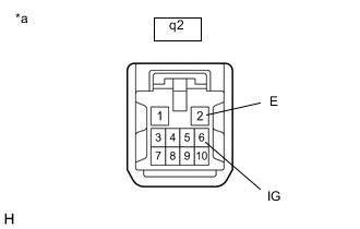
*a Front view of wire harness connector
(to roof sunshade ECU (sliding roof drive gear assembly))
Disconnect the q2 roof sunshade ECU (sliding roof drive gear assembly) connector.
-
Measure the voltage according to the value(s) in the table below.
Standard Voltage Tester Connection Condition Specified Condition q2-6 (IG) - Body ground Ignition switch ON 11 to 14 V q2-6 (IG) - Body ground Ignition switch off Below 1 V -
Measure the resistance according to the value(s) in the table below.
Standard Resistance Tester Connection Condition Specified Condition q2-2 (E) - Body ground Always Below 1 Ω Result Proceed to OK NG
OK
REPLACE SLIDING ROOF ECU (SLIDING ROOF DRIVE GEAR ASSEMBLY) Click here
NG
REPAIR OR REPLACE HARNESS OR CONNECTOR
-