INSTRUMENT PANEL SAFETY PAD INSTALLATION
PROCEDURE
-
INSTALL INSTRUMENT PANEL SAFETY PAD SUB-ASSEMBLY
-
When installing a new instrument panel safety pad sub-assembly:
-
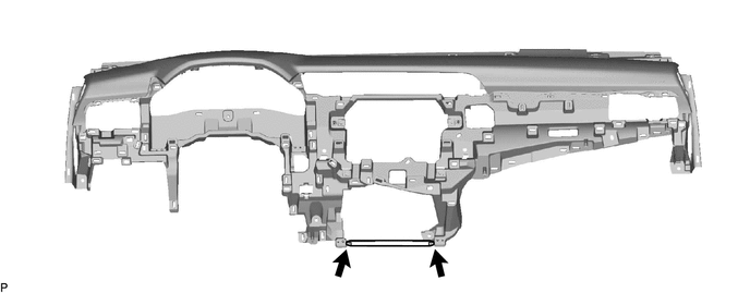
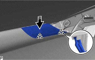
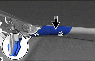
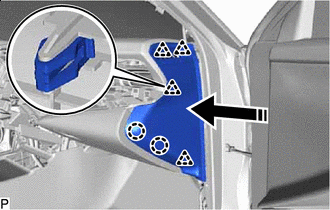
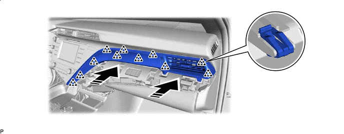
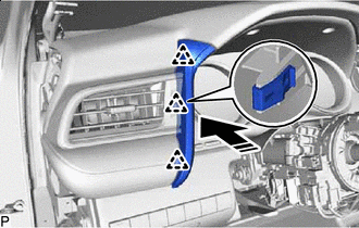
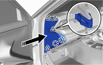
Immediately before installing the instrument panel safety pad sub-assembly, twist and cut off the portion as shown in the illustration.
-
-
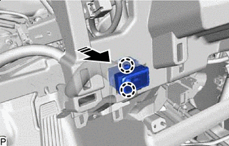
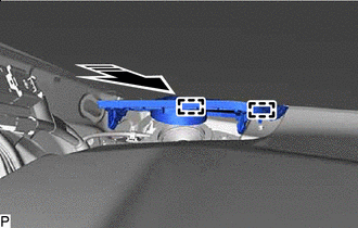
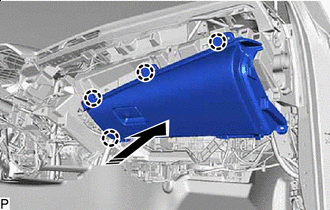
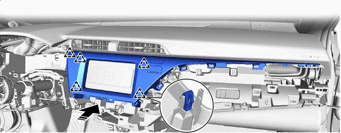
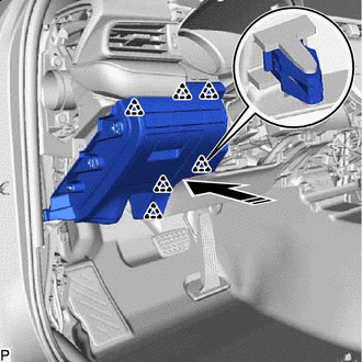
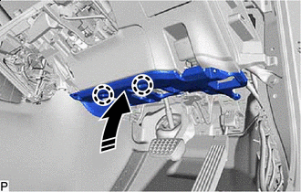
Engage the 4 guides to temporarily install the instrument panel safety pad sub-assembly as shown in the illustration.
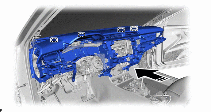

Install in this Direction - - Note
-
Do not damage the instrument panel safety pad sub-assembly.
-
Do not allow the wire harnesses to interfere with the surrounding parts.
-
-
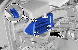
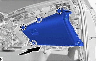
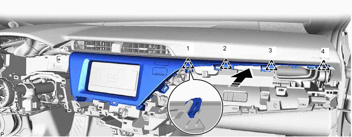
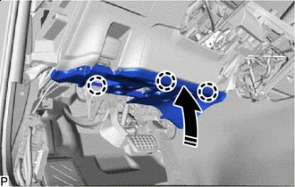
Install the instrument panel safety pad sub-assembly with the 4 bolts <B>, 2 bolts <A> and nut <F>.
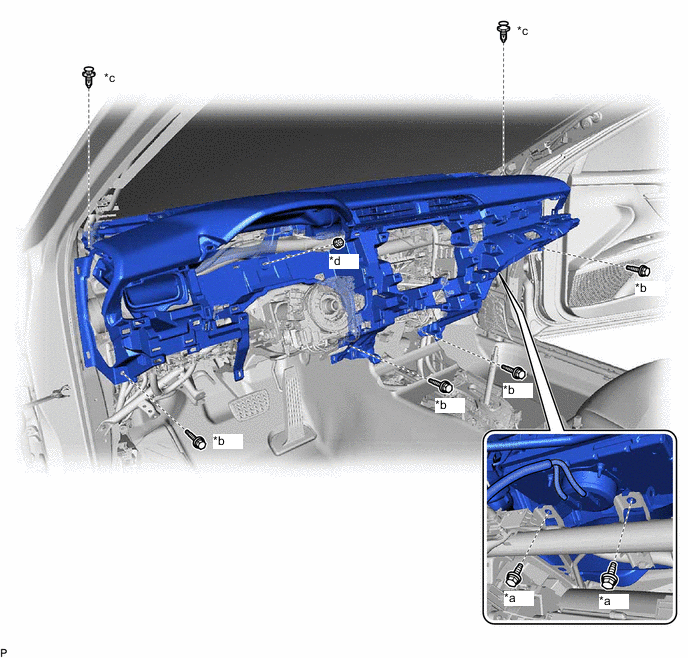
*a Bolt <A> *b Bolt <B> *c Clip *d Nut <F> - Torque:
- Bolt<A>
- 20 N*m { 204 kgf*cm, 15 ft.*lbf }
-
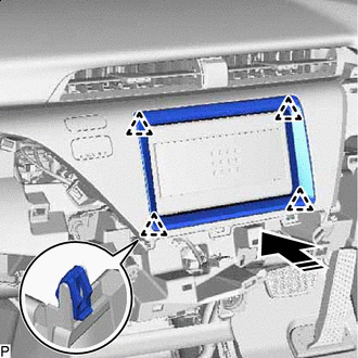
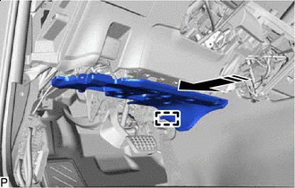
Install the 2 clips.
-
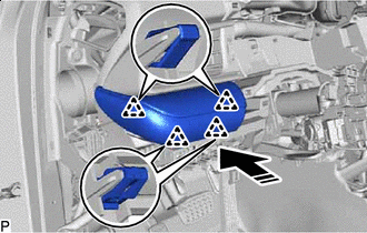
Engage each clamp.
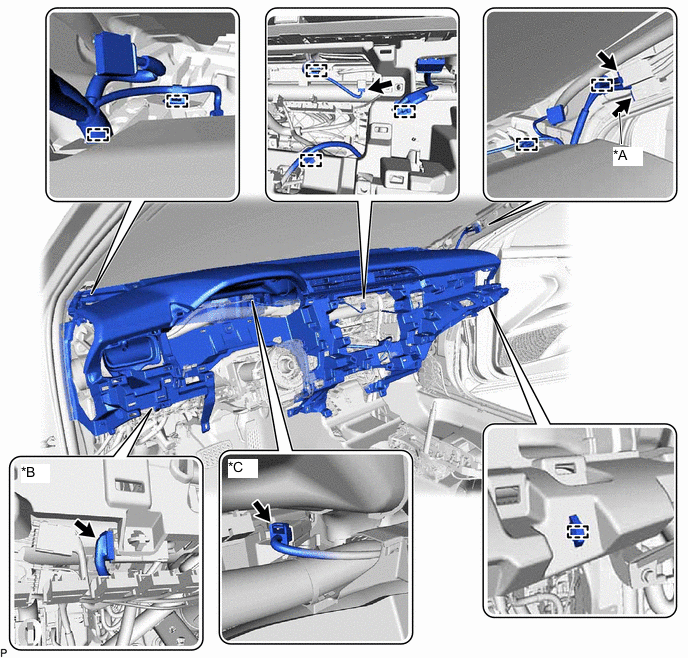
*A w/ Digital Audio Broadcasting Antenna or Television Antenna *B w/ Ion Generator *C w/ Headup Display - - -
Connect each connector.
-
for Automatic Air Conditioning System:
-
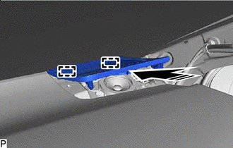
Install in this Direction Engage the 2 claws to connect the cooler (room temp. sensor) thermistor as shown in the illustration.
-
-
-
CONNECT NO. 5 INSTRUMENT PANEL WIRE (w/o Occupant Classification System)
-
CONNECT NO. 5 INSTRUMENT PANEL WIRE (w/ Occupant Classification System)
-
INSTALL NO. 1 INSTRUMENT PANEL REGISTER ASSEMBLY
-
Install in this Direction Engage the 2 clips and 2 claws to install the No. 1 instrument panel register assembly as shown in the illustration.
-
-
INSTALL NO. 1 INSTRUMENT PANEL GARNISH SUB-ASSEMBLY
-
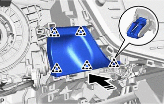
Install in this Direction Engage the 4 clips to install the No. 1 instrument panel garnish sub-assembly as shown in the illustration.
-
-
INSTALL FRONT NO. 2 SPEAKER ASSEMBLY (for RH Side)
-
INSTALL NO. 2 INSTRUMENT PANEL SPEAKER PANEL
-
Install in this Direction Engage the 2 guides as shown in the illustration.
-
Install in this Direction Engage the 2 clips to install the No. 2 instrument panel speaker panel as shown in the illustration.
-
-
INSTALL FRONT NO. 2 SPEAKER ASSEMBLY (for LH Side)
-
INSTALL NO. 1 INSTRUMENT PANEL SPEAKER PANEL
-
Install in this Direction Engage the 2 guides as shown in the illustration.
-
Install in this Direction Engage the 2 clips to install the No. 1 instrument panel speaker panel as shown in the illustration.
-
-
INSTALL LOWER INSTRUMENT PANEL SUB-ASSEMBLY (w/o Passenger Side Knee Airbag)
-
Connect the connector.
-
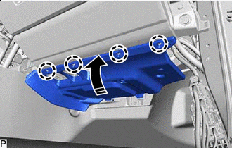
Install in this Direction Engage the 4 claws as shown in the illustration.
-
Install the 2 bolts <D>.
- Torque:
- 10 N*m { 102 kgf*cm, 7 ft.*lbf }
-
Install the lower instrument panel sub-assembly with the 3 screws <C>.
-
-
INSTALL LOWER INSTRUMENT PANEL SUB-ASSEMBLY (w/ Passenger Side Knee Airbag)
-
Connect the connector.
-
Install in this Direction Engage the 4 claws as shown in the illustration.
-
Install the lower instrument panel sub-assembly with the 5 screws <C>.
-
-
INSTALL LOWER NO. 2 INSTRUMENT PANEL AIRBAG ASSEMBLY (w/ Passenger Side Knee Airbag)
-
INSTALL NO. 2 INSTRUMENT PANEL UNDER COVER SUB-ASSEMBLY
-
Connect the connector.
-
Engage the clamp.
-
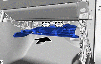
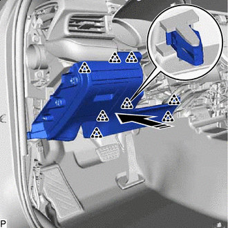
Install in this Direction Engage the 2 guides as shown in the illustration.
-
Install in this Direction Engage the 4 claws to install the No. 2 instrument panel under cover sub-assembly as shown in the illustration.
-
-
INSTALL INSTRUMENT SIDE PANEL RH
-
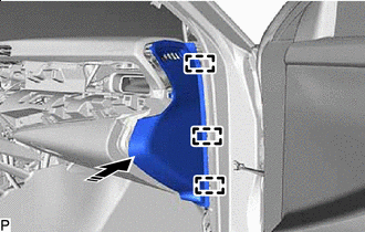
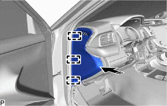
Install in this Direction Engage the 3 guides as shown in the illustration.
-
Install in this Direction Engage the 4 clips and 2 claws to install the instrument side panel RH as shown in the illustration.
-
-
INSTALL FRONT PILLAR GARNISH RH (w/o Curtain Shield Airbag)
-
INSTALL FRONT PILLAR GARNISH RH (w/ Curtain Shield Airbag)
-
INSTALL FRONT DOOR OPENING TRIM WEATHERSTRIP RH
-
INSTALL COWL SIDE TRIM SUB-ASSEMBLY RH
-
INSTALL FRONT DOOR SCUFF PLATE RH
-
INSTALL RADIO TUNER OPENING COVER WITH BRACKET (w/o Radio Receiver)
-
Connect the connector.
-
Install the radio tuner opening cover with bracket with the 4 bolts <B>.
-
-
INSTALL CENTER INSTRUMENT CLUSTER FINISH PANEL ASSEMBLY (w/o Radio Receiver)
-
Connect the connector.
-
Engage the 5 clips as shown in the illustration.
Install in this Direction - - -
Engage the 4 clips in the order shown in the illustration to install the center instrument cluster finish panel assembly.
Install in this Direction - -
-
-
INSTALL INSTRUMENT CLUSTER FINISH PANEL COVER (w/o Radio Receiver)
-
for RHD:
-
Install in this Direction Engage the 4 clips to install the instrument cluster finish panel cover as shown in the illustration.
-
-
-
INSTALL RADIO AND DISPLAY RECEIVER ASSEMBLY WITH BRACKET (for 7 Inch Display)
-
INSTALL RADIO AND DISPLAY RECEIVER ASSEMBLY WITH BRACKET (for 8 Inch Display)
-
INSTALL AIR CONDITIONING CONTROL ASSEMBLY (except 8 Inch Display)
-
INSTALL NO. 3 INSTRUMENT PANEL REGISTER ASSEMBLY
-
Connect the connector.
-
Engage the 11 clips to install the No. 3 instrument panel register assembly as shown in the illustration.
Install in this Direction - -
-
-
INSTALL LOWER INSTRUMENT PANEL FINISH PANEL ASSEMBLY
-
w/ Switch:
-
Connect the connector.
-
-
Install in this Direction Engage the 5 clips to install the lower instrument panel finish panel assembly as shown in the illustration.
-
-
INSTALL COMBINATION METER ASSEMBLY
-
INSTALL INSTRUMENT CLUSTER FINISH PANEL ASSEMBLY
-
Connect the connector.
-
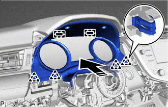
Install in this Direction Engage the 2 guides and 4 clips to install the instrument cluster finish panel assembly as shown in the illustration.
-
Install the 2 clips.
-
-
INSTALL LOWER NO. 1 INSTRUMENT PANEL AIRBAG ASSEMBLY (w/ Driver Side Knee Airbag)
for LHD:
for RHD:
-
INSTALL NO. 1 INSTRUMENT PANEL SUB-ASSEMBLY (w/o Driver Side Knee Airbag)
-
Connect each connector.
-
Engage the clamp.
-
Install in this Direction Engage the 8 clips to install the No. 1 instrument panel sub-assembly as shown in the illustration.
-
-
INSTALL NO. 1 INSTRUMENT PANEL SUB-ASSEMBLY (w/ Driver Side Knee Airbag)
-
Connect each connector.
-
Engage the clamp.
-
Install in this Direction Engage the 6 clips to install the No. 1 instrument panel sub-assembly as shown in the illustration.
-
-
CONNECT HOOD LOCK CONTROL LEVER SUB-ASSEMBLY
-
Engage the claw and 2 guides to connect the hood lock control lever sub-assembly.
-
-
INSTALL NO. 2 METER HOOD CLUSTER
-
Install in this Direction Engage the 3 clips to install the No. 2 meter hood cluster as shown in the illustration.
-
-
INSTALL NO. 1 INSTRUMENT PANEL UNDER COVER SUB-ASSEMBLY (for LHD)
-
Engage the 2 claws to connect the DLC3 connector.
-
Engage the 2 clamps.
-
Connect the connector.
-
Install in this Direction Engage the guide as shown in the illustration.
-
Install in this Direction Engage the 3 claws as shown in the illustration.
-
Install the No. 1 instrument panel under cover sub-assembly with the 2 screws <C>.
-
-
INSTALL NO. 1 INSTRUMENT PANEL UNDER COVER SUB-ASSEMBLY (for RHD)
-
Engage the 2 claws to connect the DLC3 connector.
-
Engage the clamp.
-
Connect the connector.
-
Install in this Direction Engage the 2 claws as shown in the illustration.
-
Install the No. 1 instrument panel under cover sub-assembly with the 3 screws <C>.
-
-
INSTALL INSTRUMENT SIDE PANEL LH
-
Install in this Direction Engage the 3 guides as shown in the illustration.
-
Install in this Direction Engage the 4 clips and 2 claws to install the instrument side panel LH as shown in the illustration.
-
-
INSTALL FRONT PILLAR GARNISH LH (w/o Curtain Shield Airbag)
-
INSTALL FRONT PILLAR GARNISH LH (w/ Curtain Shield Airbag)
-
INSTALL FRONT DOOR OPENING TRIM WEATHERSTRIP LH
-
INSTALL COWL SIDE TRIM SUB-ASSEMBLY LH
-
INSTALL FRONT DOOR SCUFF PLATE LH
-
INSTALL CONSOLE BOX ASSEMBLY
-
INSTALL TURN SIGNAL SWITCH
-
INSTALL WINDSHIELD WIPER SWITCH ASSEMBLY
-
INSTALL UPPER STEERING COLUMN COVER (for Manual Tilt and Manual Telescopic Steering Column)
-
INSTALL UPPER STEERING COLUMN COVER (for Power Tilt and Power Telescopic Steering Column)
-
INSTALL LOWER STEERING COLUMN COVER SUB-ASSEMBLY (for Manual Tilt and Manual Telescopic Steering Column)
-
INSTALL LOWER STEERING COLUMN COVER SUB-ASSEMBLY (for Power Tilt and Power Telescopic Steering Column)
-
ALIGN FRONT WHEELS FACING STRAIGHT AHEAD
-
INSPECT AND ADJUST SPIRAL CABLE WITH SENSOR SUB-ASSEMBLY
-
INSTALL STEERING WHEEL ASSEMBLY
-
CHECK STEERING WHEEL CENTER POINT
-
INSTALL HORN BUTTON ASSEMBLY
-
CUSTOMIZE POWER TILT AND POWER TELESCOPIC STEERING COLUMN SYSTEM (for Power Tilt and Power Telescopic Steering Column)