PROCEDURE
- Click here
INSTALL INSTRUMENT PANEL CUSHION
-
Clean the instrument panel safety pad sub-assembly surface.
-
Remove any remaining double-sided tape from the instrument panel safety pad sub-assembly.
-
Wipe off any tape adhesive residue with cleaner.
-
-
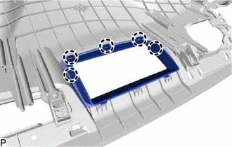
Remove the release paper from a new instrument panel cushion.
Tip:After removing the release paper, keep the exposed adhesive free from foreign matter.
-
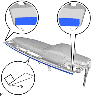
*a Edge of Curved Surface *b Outline Install the instrument panel cushion as shown in the illustration.
-
- Click here
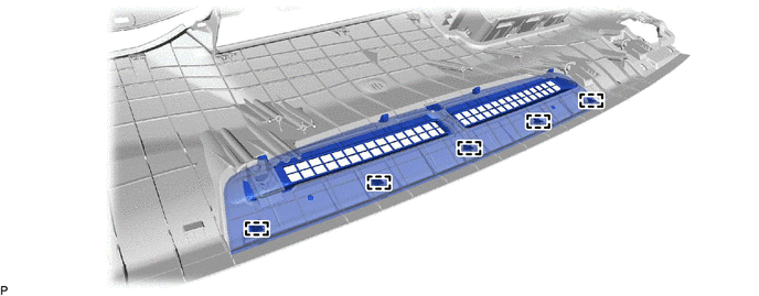
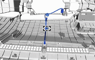
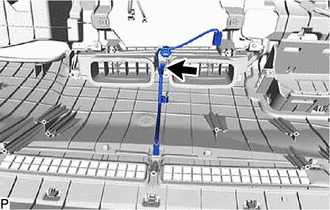
INSTALL NO. 4 INSTRUMENT PANEL WIRE (w/ Ion Generator)
-
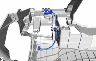
Engage the 2 clamps to install the No. 4 instrument panel wire.
-
- Click here
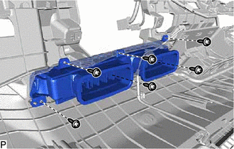
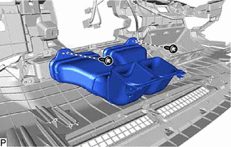
INSTALL ION GENERATOR WITH BRACKET (w/ Ion Generator)
- Click here
INSTALL AIR DUCT SUB-ASSEMBLY (w/ Ion Generator)
for RHD:
- Click here
INSTALL ANTENNA CORD SUB-ASSEMBLY (for LHD)
- Click here
INSTALL ANTENNA CORD SUB-ASSEMBLY (for RHD)
- Click here
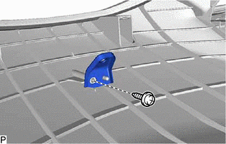
INSTALL NO. 1 INSTRUMENT PANEL PIN
-
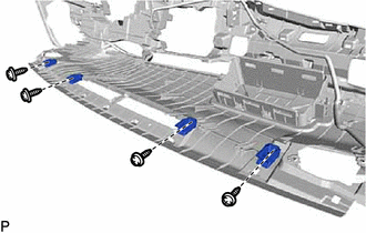
Install the 4 No. 1 instrument panel pins with the 4 screws <E>.
-
- Click here
INSTALL INSTRUMENT PANEL HOLE COVER (w/ Headup Display)
-
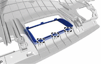
Engage the 3 guides.
-
Engage the 5 claws to install the instrument panel hole cover.
-
- Click here
INSTALL NO. 1 DEFROSTER NOZZLE GARNISH
-
Engage the 5 guides.
-

Engage the 4 clips to install the No. 1 defroster nozzle garnish.
-
- Click here
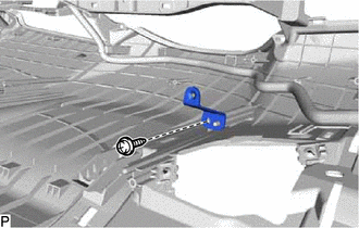
INSTALL NO. 1 METER BRACKET SUB-ASSEMBLY
-
Install the No. 1 meter bracket sub-assembly with the screw <E>.
-
- Click here
INSTALL NO. 2 METER BRACKET SUB-ASSEMBLY (w/ Headup Display)
-
Install the No. 2 meter bracket sub-assembly with the screw <E>.
-
- Click here
INSTALL NO. 3 INSTRUMENT PANEL WIRE
-
Engage the clamp to install the No. 3 instrument panel wire.
-
- Click here
INSTALL NO. 2 INSTRUMENT PANEL REGISTER ASSEMBLY
-
Install the No. 2 instrument panel register assembly with the 6 screws <E>.
-
Connect the connector.
-
- Click here
INSTALL AUTOMATIC LIGHT CONTROL SENSOR
- Click here
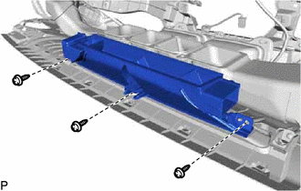
INSTALL NO. 2 HEATER TO REGISTER DUCT SUB-ASSEMBLY
-
Install the No. 2 heater to register duct sub-assembly with the 2 screws <E>.
-
- Click here
INSTALL NAVIGATION ANTENNA ASSEMBLY WITH BRACKET (w/ Navigation Antenna)
- Click here
INSTALL ANTENNA CORD SUB-ASSEMBLY (w/ Navigation Antenna)
- Click here
INSTALL NO. 3 HEATER TO REGISTER DUCT SUB-ASSEMBLY
-
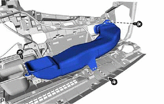
Install the No. 3 heater to register duct sub-assembly with the 3 screws <E>.
-
- Click here
INSTALL NO. 1 HEATER TO REGISTER DUCT SUB-ASSEMBLY
-
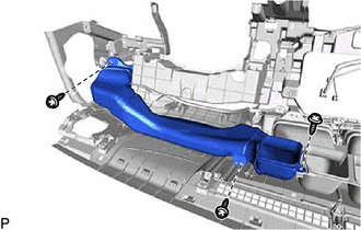
Install the No. 1 heater to register duct sub-assembly with the 3 screws <E>.
-
- Click here
INSTALL METER MIRROR SUB-ASSEMBLY (w/ Headup Display)
- Click here
INSTALL DEFROSTER NOZZLE ASSEMBLY
-
Install the defroster nozzle assembly with the 3 screws <E>.
-
- Click here
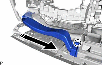
INSTALL NO. 2 SIDE DEFROSTER NOZZLE DUCT
-
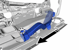

Install in this Direction Engage the claw as shown in the illustration.
-
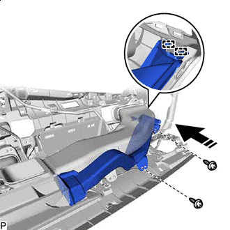
Install in this Direction Engage the 2 guides as shown in the illustration.
-
Install the No. 2 side defroster nozzle duct with the 2 screws <E>.
-
- Click here
INSTALL NO. 1 SIDE DEFROSTER NOZZLE DUCT
-
Install in this Direction Engage the claw as shown in the illustration.
-
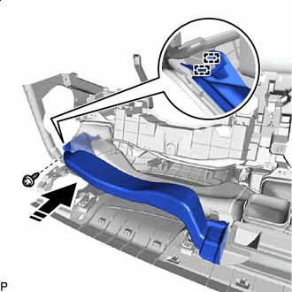
Install in this Direction Engage the 2 guides as shown in the illustration.
-
Install the No. 1 side defroster nozzle duct with the screw <E>.
-
- Click here
INSTALL INSTRUMENT PANEL PASSENGER AIRBAG ASSEMBLY
w/o Occupant Classification System:
w/ Occupant Classification System: