REAR SUNSHADE SYSTEM Rear Sunshade does not Operate with Rear Sunshade Switch
DESCRIPTION
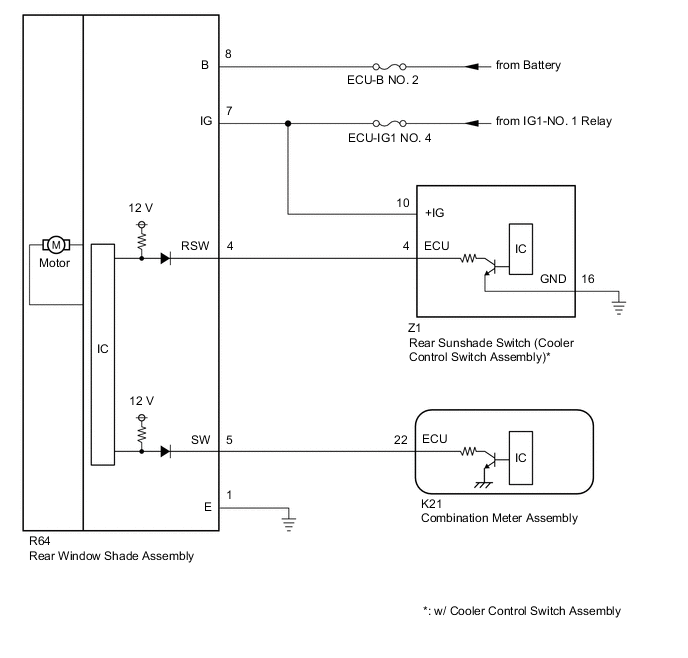
The rear window shade assembly operates according to operation signals from the combination meter assembly or rear sunshade switch (cooler control switch assembly)*.
-
*: w/ Cooler Control Switch Assembly
WIRING DIAGRAM
CAUTION / NOTICE / HINT
Note
Inspect the fuses for circuits related to this system before performing the following procedure.
PROCEDURE
-
CHECK REAR SUNSHADE OPERATION
-
Check rear sunshade manual operation.
Result Result Proceed to The rear sunshade does not operate with combination meter assembly operation. A The rear sunshade does not operate with rear sunshade switch (cooler control switch assembly) operation. (w/ Cooler Control Switch Assembly) B The rear sunshade does not operate with combination meter assembly and rear sunshade switch (cooler control switch assembly) operation. (w/ Cooler Control Switch Assembly) C
B 
CHECK REAR WINDOW SHADE ASSEMBLY Click here
C
CHECK HARNESS AND CONNECTOR (POWER SOURCE AND BODY GROUND) Click here
A 
-
-
CHECK REAR WINDOW SHADE ASSEMBLY
-
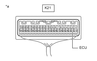
*a Component with harness connected
(Combination Meter Assembly)
Measure the voltage according to the value(s) in the table below.
Standard Voltage Tester Connection Condition Specified Condition K21-22 (ECU) - Body ground Rear window shade assembly not operating 5.5 V or higher Result Proceed to OK NG
OK 
REPLACE COMBINATION METER ASSEMBLY Click here
NG
-
-
CHECK HARNESS AND CONNECTOR (REAR WINDOW SHADE ASSEMBLY - COMBINATION METER ASSEMBLY)
-
Disconnect the R64 rear window shade assembly connector.
-
Disconnect the K21 combination meter assembly connector.
-
Measure the resistance according to the value(s) in the table below.
Standard Resistance Tester Connection Condition Specified Condition R64-5 (SW) - K21-22 (ECU) Always Below 1 Ω R64-5 (SW) or K21-22 (ECU) - Body ground Always 10 kΩ or higher Result Proceed to OK NG
OK
REPLACE REAR WINDOW SHADE ASSEMBLY Click here
NG
REPAIR OR REPLACE HARNESS OR CONNECTOR
-
-
CHECK REAR WINDOW SHADE ASSEMBLY
-
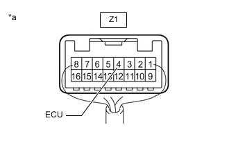
*a Component with harness connected
(Rear Sunshade Switch (Cooler Control Switch Assembly))
Measure the voltage according to the value(s) in the table below.
Standard Voltage Tester Connection Condition Specified Condition Z1-4 (ECU) - Body ground Rear window shade assembly not operating 5.5 V or higher Result Proceed to OK NG
NG
CHECK HARNESS AND CONNECTOR (REAR WINDOW SHADE ASSEMBLY - REAR SUNSHADE SWITCH (COOLER CONTROL SWITCH ASSEMBLY)) Click here
OK
-
-
CHECK HARNESS AND CONNECTOR (POWER SOURCE AND BODY GROUND)
-
Disconnect the Z1 rear sunshade switch (cooler control switch assembly) connector.
-
Measure the voltage and resistance according to the value(s) in the table below.
Standard Voltage Tester Connection Condition Specified Condition Z1-10 (+IG) - Body ground Ignition switch off Below 1 V Z1-10 (+IG) - Body ground Ignition switch ON 11 to 14 V Standard Resistance Tester Connection Condition Specified Condition Z1-16 (GND) - Body ground Always Below 1 Ω Result Proceed to OK NG
OK
REPLACE REAR SUNSHADE SWITCH (COOLER CONTROL SWITCH ASSEMBLY) Click here
NG
REPAIR OR REPLACE HARNESS OR CONNECTOR
-
-
CHECK HARNESS AND CONNECTOR (REAR WINDOW SHADE ASSEMBLY - REAR SUNSHADE SWITCH (COOLER CONTROL SWITCH ASSEMBLY))
-
Disconnect the R64 rear window shade assembly connector.
-
Disconnect the Z1 rear sunshade switch (cooler control switch assembly) connector.
-
Measure the resistance according to the value(s) in the table below.
Standard Resistance Tester Connection Condition Specified Condition R64-4 (RSW) - Z1-4 (ECU) Always Below 1 Ω R64-4 (RSW) or Z1-4 (ECU) - Body ground Always 10 kΩ or higher Result Proceed to OK NG
OK
REPLACE REAR WINDOW SHADE ASSEMBLY Click here
NG
REPAIR OR REPLACE HARNESS OR CONNECTOR
-
-
CHECK HARNESS AND CONNECTOR (POWER SOURCE AND BODY GROUND)
-
Disconnect the R64 rear window shade assembly connector.
-
Measure the voltage and resistance according to the value(s) in the table below.
Standard Voltage Tester Connection Condition Specified Condition R64-8 (B) - Body ground Always 11 to 14 V R64-7 (IG) - Body ground Ignition switch off Below 1 V R64-7 (IG) - Body ground Ignition switch ON 11 to 14 V Standard Resistance Tester Connection Condition Specified Condition R64-1 (E) - Body ground Always Below 1 Ω Result Proceed to OK NG
OK
REPLACE REAR WINDOW SHADE ASSEMBLY Click here
NG
REPAIR OR REPLACE HARNESS OR CONNECTOR
-