PROCEDURE
- Click here
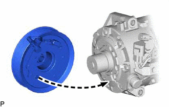
INSTALL MAGNET CLUTCH ASSEMBLY
-
Secure the cooler compressor assembly in a vise between aluminum plates.
-
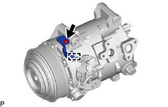
Install the magnet clutch stator with the parts aligned as shown in the illustration.
-
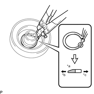
*a Chamfered Side *b Inside *c Outside Using a snap ring expander, install a new snap ring with the chamfered side facing outward.
Note:When installing the snap ring, do not widen it excessively.
-
Connect the connector.
-
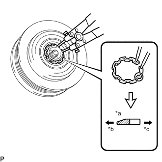
*a Chamfered Side *b Inside *c Outside Using a snap ring expander, install the magnet clutch rotor and a new snap ring with the chamfered side facing outward.
Note:
-
Do not damage the seal cover of the bearing when installing the snap ring.
-
When installing the snap ring, do not widen it excessively.
-
-
Install the magnet clutch washer(s) and magnet clutch hub.
Note:Use the same magnet clutch washer(s) as removed during disassembly.
-
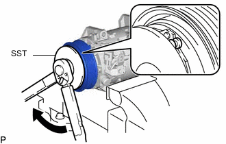
Using SST, hold the magnet clutch hub and install the bolt.
09985-00270 18 N*m 184 kgf*cm 13 ft.*lbf Note:Make sure that there is no foreign matter or oil on the compressor shaft, bolt and magnet clutch hub before installing the bolt.
-
- Click here
INSPECT MAGNET CLUTCH CLEARANCE
-
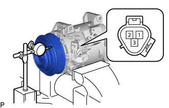
Set a dial indicator to the magnet clutch hub.
-
Connect a positive (+) lead from the battery to terminal 3 of the magnet clutch connector and a negative (-) lead to the ground wire. Turn the magnet clutch on and off and measure the clearance.
Standard Clearance 0.35 to 0.60 mm (0.0138 to 0.0236 in.) If the measured value is not within the standard clearance, remove the magnet clutch hub and adjust the clearance using magnet clutch washers to obtain the standard clearance.
Magnet Clutch Washer Thickness 0.1 mm (0.00394 in.) 0.3 mm (0.0118 in.) 0.5 mm (0.0197 in.) Note:Adjustment should be performed with 3 or fewer magnet clutch washers.
-
Remove the compressor assembly and magnetic clutch from the vise.
-
- Click here
INSTALL COOLER COMPRESSOR BRACKET
-
Install the cooler compressor bracket with the screw.
-
Engage the clamp.
-