AIR CONDITIONING SYSTEM(for Manual Air Conditioning System), Diagnostic DTC:B1449
| DTC Code | DTC Name |
|---|---|
| B1449 | Air Outlet Damper Control Servo Motor Circuit (Rear) |
DESCRIPTION
The No. 2 air conditioning radiator damper servo sub-assembly sends pulse signals to inform the air conditioning amplifier assembly of the damper position. The air conditioning amplifier assembly activates the motor (normal or reverse) based on these signals to move the air outlet damper to the appropriate position, which controls the rear air outlet switching. The air conditioning amplifier assembly communicates with the servo through a communication/driver IC and wiring assembly called the air conditioning harness assembly.
| DTC No. | Detection Item | DTC Detection Condition | Trouble Area | Memory |
|---|---|---|---|---|
| B1449 | Air Outlet Damper Control Servo Motor Circuit (Rear) | Air outlet damper position sensor value does not change even if air conditioning amplifier assembly operates No. 2 air conditioning radiator damper servo sub-assembly |
|
Memorized (30 sec. or more)* |
-
*: The air conditioning amplifier assembly stores this DTC if the malfunction has occurred for the period of time indicated in the brackets.
| Vehicle Condition | |||
|---|---|---|---|
| Pattern 1 | Pattern 2 | ||
| Diagnosis Condition | No. 2 air conditioning radiator damper servo sub-assembly operating | ○ | ○ |
| Malfunction | Air outlet damper servo operation request signals are output but the rear passenger side air outlet damper position sensor value does not change | ○ | - |
| Air outlet damper servo operation request signals are output but the rear passenger side air outlet damper position sensor value is abnormal | - | ○ | |
| Detection Time | Continuously for 30 seconds or more | Continuously for 30 seconds or more | |
| Trip Count | 1 trip | 1 trip | |
Tech Tips
If the conditions of either of these patterns are detected, a DTC will be stored.
WIRING DIAGRAM
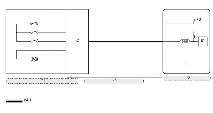
| *1 | No. 2 Air Conditioning Radiator Damper Servo Sub-assembly |
| *2 | Air Conditioning Amplifier Assembly |
| *3 | Air Conditioning Harness Assembly |
| *4 | LIN Communication Line |
CAUTION / NOTICE / HINT
Tech Tips
-
Confirm that no mechanical problems are present because this DTC can be stored when either a damper link or damper is mechanically locked.
-
When installing a damper servo motor, make sure to install it correctly.
-
After replacing a damper servo motor, make sure to perform Servo Motor Initialization.
PROCEDURE
-
CHECK FOR DTC
-
Check for DTCs.
Body Electrical > Air Conditioner > Trouble CodesResult Result Proceed to B1497 is not output A B1497 is output B
B 
GO TO DTC B1497 Click here
A 
-
-
INSPECT NO. 2 AIR CONDITIONING RADIATOR DAMPER SERVO SUB-ASSEMBLY (INSTALLATION CONDITION)
-
Check that the No. 2 air conditioning radiator damper servo sub-assembly is installed correctly.
OK The No. 2 air conditioning radiator damper servo sub-assembly is installed correctly. Result Proceed to OK NG
NG
INSTALL NO. 2 AIR CONDITIONING RADIATOR DAMPER SERVO SUB-ASSEMBLY CORRECTLY Click here
OK
-
-
INSPECT NO. 2 AIR CONDITIONING RADIATOR DAMPER SERVO SUB-ASSEMBLY (MOTOR, LINK, DAMPER)
-
Check for a wire harness caught between the links of the motors and dampers.
OK No wire harnesses are caught between the links of the motors and dampers. Result Proceed to OK NG
NG
REMOVE PINCHED WIRE HARNESS
OK
-
-
INSPECT NO. 2 AIR CONDITIONING RADIATOR DAMPER SERVO SUB-ASSEMBLY (DAMPER)
-
Remove the No. 2 air conditioning radiator damper servo sub-assembly.
-
Operate the dampers by hand.
OK The dampers are easily operated by hand. Result Proceed to OK NG
NG
REPLACE AIR CONDITIONING RADIATOR ASSEMBLY Click here
OK
-
-
PERFORM ACTIVE TEST USING GTS
-
Remove the No. 1 air conditioning radiator damper servo sub-assembly.
-
Connect the No. 1 air conditioning radiator damper servo sub-assembly connector to the No. 2 air conditioning radiator damper servo sub-assembly.
-
Connect the GTS to the DLC3.
-
Turn the ignition switch to ON.
-
Turn the GTS on.
-
Enter the following menus: Body Electrical / Air Conditioner / Active Test.
-
Perform the Active Test according to the display on the GTS.
Body Electrical > Air Conditioner > Active TestTester Display Measurement Item Control Range Diagnostic Note Air Outlet Servo Pulse (D) No. 1 air conditioning radiator damper servo sub-assembly (mode) pulse* Min.: 128
Max.: 383
Operates between 241 to 348 pulses
-
*: Though this Active Test is for the No. 1 air conditioning radiator damper servo sub-assembly, in this case it is used to check the operation of the No. 2 air conditioning radiator damper servo sub-assembly.
Body Electrical > Air Conditioner > Active TestTester Display Air Outlet Servo Pulse (D) OK The No. 2 air conditioning radiator damper servo sub-assembly operates. Result Proceed to OK NG -
OK
REPLACE AIR CONDITIONING HARNESS ASSEMBLY Click here
NG
REPLACE NO. 2 AIR CONDITIONING RADIATOR DAMPER SERVO SUB-ASSEMBLY Click here
-