AIR CONDITIONING SYSTEM(for Manual Air Conditioning System), Diagnostic DTC:B14B2
| DTC Code | DTC Name |
|---|---|
| B14B2 | Lost Communication with Front Panel LIN |
DESCRIPTION
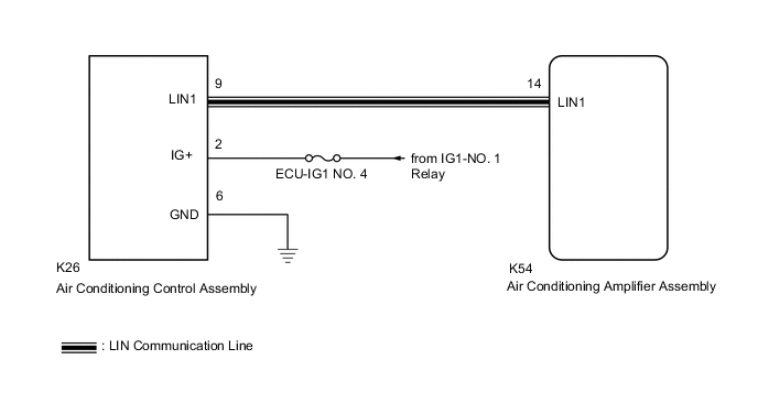
The air conditioning control assembly communicates with the air conditioning amplifier assembly via LIN communication.
If a malfunction occurs in the LIN communication system, the air conditioning amplifier assembly will not operate, even if the air conditioning control assembly is operated.
| DTC No. | Detection Item | DTC Detection Condition | Trouble Area | Memory |
|---|---|---|---|---|
| B14B2 | Lost Communication with Front Panel LIN | Lost communication with air conditioning control assembly |
|
Memorized (10 sec. or more)* |
-
*: The air conditioning amplifier assembly stores this DTC if the malfunction has occurred for the period of time indicated in the brackets.
WIRING DIAGRAM
PROCEDURE
-
CHECK HARNESS AND CONNECTOR (AIR CONDITIONING CONTROL ASSEMBLY - IG POWER SOURCE)
-
Disconnect the K26 air conditioning control assembly connector.
-
Measure the voltage according to the value(s) in the table below.
Standard Voltage Tester Connection Condition Specified Condition K26-2 (IG+) - Body ground Ignition switch ON 11 to 14 V K26-2 (IG+) - Body ground Ignition switch off Below 1 V Result Proceed to OK NG
NG 
REPAIR OR REPLACE HARNESS OR CONNECTOR
OK 
-
-
CHECK HARNESS AND CONNECTOR (AIR CONDITIONING CONTROL ASSEMBLY - BODY GROUND)
-
Measure the resistance according to the value(s) in the table below.
Standard Resistance Tester Connection Condition Specified Condition K26-6 (GND) - Body ground Always Below 1 Ω Result Proceed to OK NG
NG
REPAIR OR REPLACE HARNESS OR CONNECTOR
OK
-
-
CHECK HARNESS AND CONNECTOR (AIR CONDITIONING CONTROL ASSEMBLY - AIR CONDITIONING AMPLIFIER ASSEMBLY)
-
Disconnect the K54 air conditioning amplifier assembly connector.
-
Measure the resistance according to the value(s) in the table below.
Standard Resistance Tester Connection Condition Specified Condition K26-9 (LIN1) - K54-14 (LIN1) Always Below 1 Ω K26-9 (LIN1) or K54-14 (LIN1) - Other terminals and body ground Always 10 kΩ or higher Result Proceed to OK NG
NG
REPAIR OR REPLACE HARNESS OR CONNECTOR
OK
-
-
INSPECT AIR CONDITIONING AMPLIFIER ASSEMBLY
-
Connect the K54 air conditioning amplifier assembly connector.
-
Turn the ignition switch to ON.
-
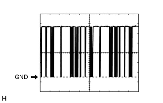
Using an oscilloscope, check the waveform.
OK Waveform is similar to that shown in the illustration. Item Content Terminal No. K54-14 (LIN1) - Body ground Tool Setting 2 V/DIV., 20 ms./DIV. Condition Ignition switch ON Result Proceed to OK NG
NG
REPLACE AIR CONDITIONING AMPLIFIER ASSEMBLY Click here
OK
-
-
INSPECT AIR CONDITIONING CONTROL ASSEMBLY
-
Connect the K26 air conditioning control assembly connector.
-
Turn the ignition switch to ON.
-
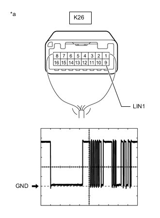
Using an oscilloscope, check the waveform.
OK Waveform is similar to that shown in the illustration. Item Content Terminal No. K26-9 (LIN1) - Body ground Tool Setting 2 V/DIV., 20 ms./DIV. Condition Ignition switch ON Result Proceed to OK NG
OK
REPLACE AIR CONDITIONING AMPLIFIER ASSEMBLY Click here
NG
REPLACE AIR CONDITIONING CONTROL ASSEMBLY Click here
-