AIR CONDITIONING SYSTEM(for Automatic Air Conditioning System) Operation not Accepted Even If Air Conditioning Switch is Operated
DESCRIPTION
If the air conditioning system cannot be operated using the air conditioning control panel (radio and display receiver assembly)*1 or air conditioning control assembly*2, the following factors may be the cause.
| Symptom | Factor |
|---|---|
| Air conditioning system cannot be operated using air conditioning control panel (radio and display receiver assembly)*1 or air conditioning control assembly*2
|
|
-
*1: w/ Radio and Display Receiver
-
*2: w/o Radio and Display Receiver
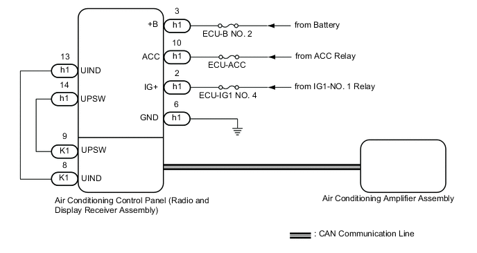
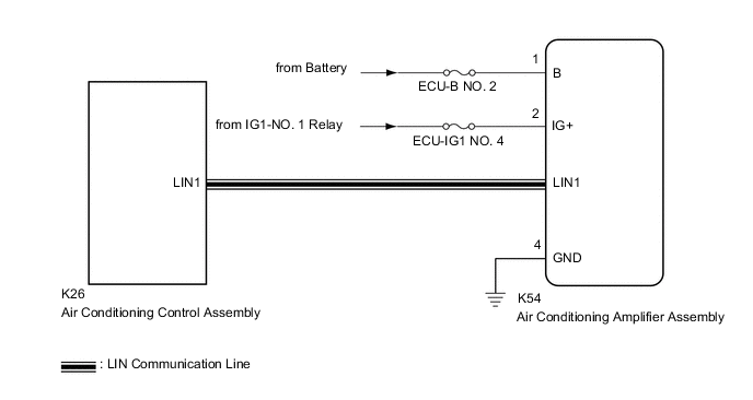
WIRING DIAGRAM
-
w/ Radio and Display Receiver
-
w/o Radio and Display Receiver
CAUTION / NOTICE / HINT
Note
Inspect the fuses for circuits related to this system before performing the following procedure.
PROCEDURE
-
CONFIRM MODEL
Result Result Proceed to w/ Radio and Display Receiver A w/o Radio and Display Receiver B
B 
CHECK FOR DTC Click here
A 
-
CHECK HARNESS AND CONNECTOR (RADIO AND DISPLAY RECEIVER ASSEMBLY - POWER SOURCE AND BODY GROUND)
-
Disconnect the h1 air conditioning control panel (radio and display receiver assembly) connector.
-
Measure the voltage and resistance according to the value(s) in the table below.
Standard Voltage Tester Connection Condition Specified Condition h1-3 (+B) - Body ground Always 11 to 14 V h1-10 (ACC) - Body ground Ignition switch ACC 11 to 14 V h1-2 (IG+) - Body ground Ignition switch ON 11 to 14 V Standard Resistance Tester Connection Condition Specified Condition h1-6 (GND) - Body ground Always Below 1 Ω Result Proceed to OK NG
NG 
REPAIR OR REPLACE HARNESS OR CONNECTOR
OK
-
-
CHECK FOR DTC (AUDIO AND VISUAL SYSTEM)
-
Check for DTCs.
Body Electrical > Navigation System > Trouble CodesOK DTC B15F9 is not output. Result Proceed to OK NG
NG
REPLACE AIR CONDITIONING CONTROL PANEL (RADIO AND DISPLAY RECEIVER ASSEMBLY) Click here
OK
-
-
CHECK FOR DTC (CAN COMMUNICATION SYSTEM)
-
Using the GTS, check for CAN communication system DTCs.
Result Result Proceed to CAN communication system DTCs are not output A CAN communication system DTCs are output B
B
GO TO CAN COMMUNICATION SYSTEM Click here
A
-
-
PERFORM ACTIVE TEST USING GTS
-
Connect the GTS to the DLC3.
-
Turn the ignition switch to ON.
-
Turn the GTS on.
-
Enter the following menus: Body Electrical / Air Conditioner / Active Test.
-
Perform the Active Test according to the display on the GTS.
Body Electrical > Air Conditioner > Active TestTester Display Measurement Item Control Range Diagnostic Note Blower Motor Blower motor with fan sub-assembly Min.: 0
Max.: 31
-
Body Electrical > Air Conditioner > Active TestTester Display Blower Motor OK Blower motor with fan sub-assembly operates normally. Result Proceed to OK NG
OK
REPLACE AIR CONDITIONING CONTROL PANEL (RADIO AND DISPLAY RECEIVER ASSEMBLY) Click here
NG
REPLACE AIR CONDITIONING AMPLIFIER ASSEMBLY Click here
-
-
CHECK FOR DTC
-
Check for DTCs.
Body Electrical > Air Conditioner > Trouble CodesOK DTC B14B2 is not output. Result Proceed to OK NG
NG
GO TO DTC B14B2 Click here
OK
-
-
CHECK HARNESS AND CONNECTOR (AIR CONDITIONING AMPLIFIER ASSEMBLY - POWER SOURCE AND BODY GROUND)
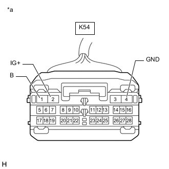
*a Front view of wire harness connector
(to Air Conditioning Amplifier Assembly)
-
Disconnect the K54 air conditioning amplifier assembly connector.
-
Measure the resistance according to the value(s) in the table below.
Standard Resistance Tester Connection Condition Specified Condition K54-4 (GND) - Body ground Always Below 1 Ω -
Measure the voltage according to the value(s) in the table below.
Standard Voltage Tester Connection Condition Specified Condition K54-1 (B) - Body ground Always 11 to 14 V K54-2 (IG+) - Body ground Ignition switch ON 11 to 14 V Ignition switch off Below 1 V Result Proceed to OK NG
OK
REPLACE AIR CONDITIONING AMPLIFIER ASSEMBLY Click here
NG
REPAIR OR REPLACE HARNESS OR CONNECTOR
-