AIR CONDITIONING SYSTEM(for Automatic Air Conditioning System) Cooling is Poor
DESCRIPTION
If the cooling effect of the air conditioning system is weak, the following factors may be the cause.
| Symptom | Factor |
|---|---|
|
|
-
*1: w/ ECO Switch
-
*2: except 2GR-FKS
-
*3: for 2GR-FKS
WIRING DIAGRAM
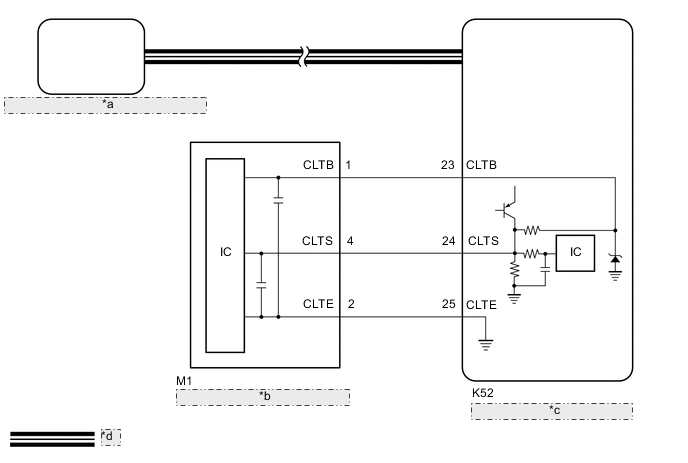
| *a | Air Conditioning Amplifier Assembly |
| *b | Automatic Light Control Sensor |
| *c | Main Body ECU (Multiplex Network Body ECU) |
| *d | CAN Communication Line |
PROCEDURE
-
CONFIRM MODEL
Result Result Proceed to w/ ECO Switch A w/o ECO Switch B
B 
GO TO STEP 3 Click here
A 
-
CHECK ECO MODE CONTROL OPERATION
-
Check that ECO mode control is disabled (ECO mode indicator is not illuminated).
-
Operate the ECO switch assembly (electric parking brake switch assembly) and check that the ECO mode indicator illuminates and the blower speed is reduced.
Tech Tips
-
When ECO mode control is operating, the air conditioning amplifier assembly controls the air conditioning system to enhance fuel efficiency. Therefore, explain to the customer that, when ECO mode control is operating, the blower speed will be reduced.
Control Outline Blower Control When the air conditioning system is in AUTO mode, the blower speed will be reduced to a certain speed. Additionally, if warm-up control is operating, the blower speed will be further reduced. Air Inlet Control If the ambient temperature is a certain value or more, the air inlet mode will be changed to recirculation mode. -
In some situations, ECO mode control may not operate even though it is enabled.
-
-
Operate the ECO switch assembly (electric parking brake switch assembly) and check that the ECO mode indicator turns off and the blower speed returns to normal.
OK When the ECO switch assembly (electric parking brake switch assembly) is operated, ECO mode control is enabled/disabled and the blower speed is controlled. Result Proceed to OK NG
NG 
GO TO ECO Switch Circuit Click here
OK
-
-
PERFORM REFRIGERANT SHORTAGE CHECK
-
Connect the GTS to the DLC3.
-
Turn the ignition switch to ON.
-
Turn the GTS on.
-
Enter the following menus: Body Electrical / Air Conditioner / Utility / Refrigerant Gas Volume Check.
Body Electrical > Air Conditioner > UtilityTester Display Refrigerant Gas Volume Check -
Check that the following conditions are met and perform the refrigerant shortage check according to the display on the GTS.
Measurement Condition: Item Condition A/C switch On Ambient temperature* 0 to 49°C (32 to 120°F) Blower speed HI *: If the ambient temperature is not within the range shown, do not perform this check.
Result Result Amount of Refrigerant Refrigerant correct Correct Refrigerant shortage Insufficient OK "Refrigerant correct" is displayed on the GTS. Result Proceed to OK NG
NG
REPAIR REFRIGERANT LEAK Click here
OK
-
-
PERFORM ACTIVE TEST USING GTS
-
Connect the GTS to the DLC3.
-
Turn the ignition switch to ON.
-
Turn the GTS on.
-
Enter the following menus: Body Electrical / Air Conditioner / Active Test.
-
Perform the Active Test according to the display on the GTS.
Body Electrical > Air Conditioner > Active TestTester Display Measurement Item Control Range Diagnostic Note Air Mix Servo Targ Pulse(D) No. 1 air conditioning radiator damper servo sub-assembly (driver side air mix) pulse Min.: 128
Max.: 383
-
Operates between 165 to 257 pulses
for LHD
-
Operates between 255 to 347 pulses
for RHD
Air Mix Servo Targ Pulse(P) No. 1 air conditioning radiator damper servo sub-assembly (front passenger side air mix) pulse Min.: 128
Max.: 383
-
Operates between 255 to 347 pulses
for LHD:
-
Operates between 165 to 257 pulses
for RHD:
Rear Air Mix Servo Targ Pulse No. 3 air conditioning radiator damper servo sub-assembly pulse Min.: 128
Max.: 383
-
Operates between 165 to 257 pulses
-
*
-
*: for 3 Zone Type
Body Electrical > Air Conditioner > Active TestTester Display Air Mix Servo Targ Pulse(D)
Body Electrical > Air Conditioner > Active TestTester Display Air Mix Servo Targ Pulse(P)
Body Electrical > Air Conditioner > Active TestTester Display Rear Air Mix Servo Targ Pulse OK Each damper servo motor operates. Result Proceed to OK NG -
NG
GO TO DTC TROUBLESHOOTING PROCEDURE FOR MALFUNCTIONING DAMPER SERVO MOTOR Click here
OK
-
-
INSPECT HARNESS AND CONNECTOR (AUTOMATIC LIGHT CONTROL SENSOR - MAIN BODY ECU (MULTIPLEX NETWORK BODY ECU))
-
Disconnect the M1 automatic light control sensor connector.
-
Disconnect the K52 main body ECU (multiplex network body ECU) connector.
-
Measure the resistance according to the value(s) in the table below.
Standard Resistance Tester Connection Condition Specified
Condition
M1-1 (CLTB) - K52-23 (CLTB) Always Below 1 Ω M1-2 (CLTE) - K52-25 (CLTE) Always Below 1 Ω M1-4 (CLTS) - K52-24 (CLTS) Always Below 1 Ω M1-1 (CLTB) or K52-23 (CLTB) - Other terminals and body ground Always 10 kΩ or higher M1-2 (CLTE) or K52-25 (CLTE) - Other terminals and body ground Always 10 kΩ or higher M1-4 (CLTS) or K52-24 (CLTS) - Other terminals and body ground Always 10 kΩ or higher Result Proceed to OK NG
NG
REPAIR OR REPLACE HARNESS OR CONNECTOR
OK
-
-
INSPECT AUTOMATIC LIGHT CONTROL SENSOR
-
Remove the automatic light control sensor.
-
Inspect the automatic light control sensor.
Result Proceed to OK NG
OK
INSPECT REFRIGERANT PRESSURE WITH MANIFOLD GAUGE SET Click here
NG
REPLACE AUTOMATIC LIGHT CONTROL SENSOR Click here
-