AIR CONDITIONING SYSTEM(for Automatic Air Conditioning System) ECO Switch Circuit
DESCRIPTION
When the ECO switch assembly (electric parking brake switch assembly) is operated, the air conditioning amplifier assembly receives a signal and enables or disables ECO mode control of the air conditioning system.
| Symptom | Factor |
|---|---|
| When ECO switch assembly (electric parking brake switch assembly) is operated, blower speed does not change |
|
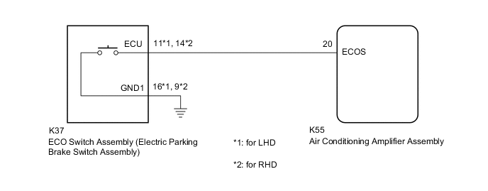
WIRING DIAGRAM
PROCEDURE
-
READ VALUE USING GTS
-
Connect the GTS to the DLC3.
-
Turn the ignition switch to ON.
-
Turn the GTS on.
-
Enter the following menus: Body Electrical / Air Conditioner / Data List.
-
Read the Data List according to the display on the GTS.
Body Electrical > Air Conditioner > Data ListTester Display Measurement Item Range Normal Condition Diagnostic Note ECO Switch ECO switch assembly (electric parking brake switch assembly) OFF or ON OFF: ECO switch assembly (electric parking brake switch assembly) not pushed
ON: ECO switch assembly (electric parking brake switch assembly) pushed and held
ECO switch assembly (electric parking brake switch assembly) circuit malfunction
Body Electrical > Air Conditioner > Data ListTester Display ECO Switch OK ECO switch assembly (electric parking brake switch assembly) condition displayed on the GTS changes with the actual switch operation. Result Proceed to OK NG
OK 
REPLACE AIR CONDITIONING AMPLIFIER ASSEMBLY Click here
NG 
-
-
INSPECT ECO SWITCH ASSEMBLY (ELECTRIC PARKING BRAKE SWITCH ASSEMBLY)
-
Remove the ECO switch assembly (electric parking brake switch assembly).
-
Inspect the ECO switch assembly (electric parking brake switch assembly).
Result Proceed to OK NG
NG
REPLACE ECO SWITCH ASSEMBLY (ELECTRIC PARKING BRAKE SWITCH ASSEMBLY) Click here
OK
-
-
CHECK HARNESS AND CONNECTOR (ECO SWITCH ASSEMBLY (ELECTRIC PARKING BRAKE SWITCH ASSEMBLY) - AIR CONDITIONING AMPLIFIER ASSEMBLY AND BODY GROUND)
-
Disconnect the K55 air conditioning amplifier assembly connector.
-
Measure the resistance according to the value(s) in the table below.
Standard Resistance for LHD: Tester Connection Condition Specified Condition K37-11 (ECU) - K55-20 (ECOS) Always Below 1 Ω K37-16 (GND1) - Body ground Always Below 1 Ω K37-11 (ECU) or K55-20 (ECOS) - Other terminals and body ground Always 10 kΩ or higher for RHD: Tester Connection Condition Specified Condition K37-14 (ECU) - K55-20 (ECOS) Always Below 1 Ω K37-9 (GND1) - Body ground Always Below 1 Ω K37-14 (ECU) or K55-20 (ECOS) - Other terminals and body ground Always 10 kΩ or higher Result Proceed to OK NG
OK
REPLACE AIR CONDITIONING AMPLIFIER ASSEMBLY Click here
NG
REPAIR OR REPLACE HARNESS OR CONNECTOR
-