AIR CONDITIONING SYSTEM(for Automatic Air Conditioning System) Air Conditioning Compressor Magnetic Clutch Circuit
DESCRIPTION
When the engine is running, If refrigerant pressure does not decrease when the A/C switch is turned off, the following factors may be the cause.
| Symptom | Factor |
|---|---|
|
|
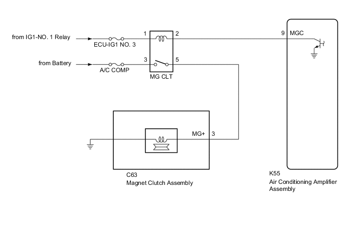
WIRING DIAGRAM
CAUTION / NOTICE / HINT
Note
Inspect the fuses for circuits related to this system before performing the following procedure.
PROCEDURE
-
INSPECT MAGNETIC CLUTCH RELAY
-
Remove the magnetic clutch relay.
-
Inspect the magnetic clutch relay.
Result Proceed to OK NG
NG 
REPLACE MAGNETIC CLUTCH RELAY
OK 
-
-
CHECK HARNESS AND CONNECTOR (MAGNETIC CLUTCH RELAY - POWER SOURCE)
-
Measure the voltage according to the value(s) in the table below.
Standard Voltage Tester Connection Condition Specified Condition 3 (MG CLT relay) - Body ground Always 11 to 14 V 1 (MG CLT relay) - Body ground Ignition switch off Below 1 V 1 (MG CLT relay) - Body ground Ignition switch ON 11 to 14 V Result Proceed to OK NG
NG
REPAIR OR REPLACE HARNESS OR CONNECTOR
OK
-
-
CHECK HARNESS AND CONNECTOR (MAGNETIC CLUTCH RELAY - AIR CONDITIONING AMPLIFIER ASSEMBLY)
-
Disconnect the K55 air conditioning amplifier assembly connector.
-
Measure the resistance according to the value(s) in the table below.
Standard Resistance Tester Connection Condition Specified Condition 2 (MG CLT relay) - K55-9 (MGC) Always Below 1 Ω 2 (MG CLT relay) or K55-9 (MGC) - Other terminals and body ground Always 10 kΩ or higher Result Proceed to OK NG
NG
REPAIR OR REPLACE HARNESS OR CONNECTOR
OK
-
-
CHECK HARNESS AND CONNECTOR (MAGNETIC CLUTCH RELAY - MAGNET CLUTCH ASSEMBLY AND BODY GROUND)
-
Disconnect the C63 magnet clutch assembly connector.
-
Measure the resistance according to the value(s) in the table below.
Standard Resistance Tester Connection Condition Specified Condition 5 (MG CLT relay) - C63-3 (MG+) Always Below 1 Ω 5 (MG CLT relay) or C63-3 (MG+) - Other terminals and body ground Always 10 kΩ or higher Result Proceed to OK NG
NG
REPAIR OR REPLACE HARNESS OR CONNECTOR
OK
-
-
CHECK HARNESS AND CONNECTOR (MAGNET CLUTCH ASSEMBLY - BODY GROUND)
-
Install the magnetic clutch relay.
-
Connect the C63 magnet clutch assembly connector.
-
Measure the voltage according to the value(s) in the table below.
Standard Voltage Tester Connection Condition Specified Condition C63-3 (MG+) - Body ground Engine running
(A/C switch: Off)
Below 1 V Result Proceed to OK NG
OK
REPLACE MAGNET CLUTCH ASSEMBLY Click here
NG
REPAIR OR REPLACE HARNESS OR CONNECTOR
-