AIR CONDITIONING SYSTEM(for Automatic Air Conditioning System), Diagnostic DTC:B1451
| DTC Code | DTC Name |
|---|---|
| B1451 | Compressor Solenoid Circuit |
DESCRIPTION
In this circuit, the compressor assembly with pulley (compressor solenoid)*1 or cooler compressor assembly (compressor solenoid)*2 receives refrigerant compression demand signals from the air conditioning amplifier assembly.
Based on this signal, the compressor assembly with pulley (compressor solenoid)*1 or cooler compressor assembly (compressor solenoid)*2 changes the amount of compressor output.
| DTC No. | Detection Item | DTC Detection Condition | Trouble Area | Memory |
|---|---|---|---|---|
| B1451 | Compressor Solenoid Circuit | Open or short in compressor solenoid circuit |
|
- |
-
*1: except 2GR-FKS
-
*2: for 2GR-FKS
WIRING DIAGRAM
-
except 2GR-FKS
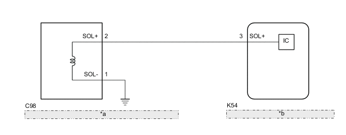
*a Compressor Assembly with Pulley (Compressor Solenoid) *b Air Conditioning Amplifier Assembly -
for 2GR-FKS
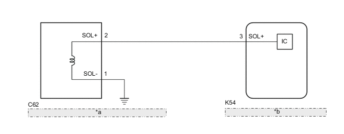
*a Cooler Compressor Assembly (Compressor Solenoid) *b Air Conditioning Amplifier Assembly
PROCEDURE
-
CONFIRM MODEL
Result Result Proceed to except 2GR-FKS A for 2GR-FKS B
B 
INSPECT AIR CONDITIONING AMPLIFIER ASSEMBLY Click here
A 
-
INSPECT AIR CONDITIONING AMPLIFIER ASSEMBLY

*a Front view of wire harness connector
(to Compressor Assembly with Pulley (Compressor Solenoid))
-
Disconnect the C98 compressor assembly with pulley (compressor solenoid) connector.
-
Using an oscilloscope, check the waveform.
Item Content Terminal No. C98-2 (SOL+) - Body ground Tool Setting 5 V/DIV., 500 μs./DIV. Condition
-
Engine running
-
Blower switch: LO
-
A/C switch: On
OK Waveform is similar to that shown in the illustration. Result Proceed to OK NG -
OK 
REPLACE COMPRESSOR ASSEMBLY WITH PULLEY (COMPRESSOR SOLENOID) for 2AR-FE: Click here
REPLACE COMPRESSOR ASSEMBLY WITH PULLEY (COMPRESSOR SOLENOID) for A25A-FKS: Click hereNG
-
-
CHECK HARNESS AND CONNECTOR (COMPRESSOR ASSEMBLY WITH PULLEY (COMPRESSOR SOLENOID) - AIR CONDITIONING AMPLIFIER ASSEMBLY)
-
Disconnect the K54 air conditioning amplifier assembly connector.
-
Measure the resistance according to the value(s) in the table below.
Standard Resistance Tester Connection Condition Specified Condition C98-2 (SOL+) - K54-3 (SOL+) Always Below 1 Ω C98-2 (SOL+) or K54-3 (SOL+) - Other terminals and body ground Always 10 kΩ or higher Result Proceed to OK NG
OK
REPLACE AIR CONDITIONING AMPLIFIER ASSEMBLY Click here
NG
REPAIR OR REPLACE HARNESS OR CONNECTOR
-
-
INSPECT AIR CONDITIONING AMPLIFIER ASSEMBLY
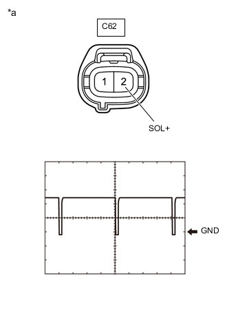
*a Front view of wire harness connector
(to Cooler Compressor Assembly (Compressor Solenoid))
-
Disconnect the C62 cooler compressor assembly (compressor solenoid) connector.
-
Using an oscilloscope, check the waveform.
Item Content Terminal No. C62-2 (SOL+) - Body ground Tool Setting 5 V/DIV., 500 μs./DIV. Condition
-
Engine running
-
Blower switch: LO
-
A/C switch: On
OK Waveform is similar to that shown in the illustration. Result Proceed to OK NG -
OK
REPLACE COOLER COMPRESSOR ASSEMBLY (COMPRESSOR SOLENOID) Click here
NG
-
-
CHECK HARNESS AND CONNECTOR (COOLER COMPRESSOR ASSEMBLY (COMPRESSOR SOLENOID) - AIR CONDITIONING AMPLIFIER ASSEMBLY)
-
Disconnect the K54 air conditioning amplifier assembly connector.
-
Measure the resistance according to the value(s) in the table below.
Standard Resistance Tester Connection Condition Specified Condition C62-2 (SOL+) - K54-3 (SOL+) Always Below 1 Ω C62-2 (SOL+) or K54-3 (SOL+) - Other terminals and body ground Always 10 kΩ or higher Result Proceed to OK NG
OK
REPLACE AIR CONDITIONING AMPLIFIER ASSEMBLY Click here
NG
REPAIR OR REPLACE HARNESS OR CONNECTOR
-