AIR CONDITIONING SYSTEM(for Automatic Air Conditioning System), Diagnostic DTC:B14B8
| DTC Code | DTC Name |
|---|---|
| B14B8 | Refrigerant Shortage |
DESCRIPTION
This DTC is stored if the amount of refrigerant in the air conditioning system is insufficient.
The air conditioning amplifier assembly receives the ambient temperature signal, refrigerant pressure signal, etc. from various sensors.
Based on these signals, the air conditioning amplifier assembly detects the amount of refrigerant.
If the amount of refrigerant is insufficient, the A/C switch indicator will turn off and the air conditioning system will stop operating.
| DTC No. | Detection Item | DTC Detection Condition | Trouble Area | Memory |
|---|---|---|---|---|
| B14B8 | Refrigerant Shortage | The following condition is detected in the normal operation refrigerant shortage check: Amount of refrigerant is insufficient |
|
Memorized (10 min. or more)* |
-
*: The air conditioning amplifier assembly stores this DTC if the malfunction has occurred for the period of time indicated in the brackets.
WIRING DIAGRAM
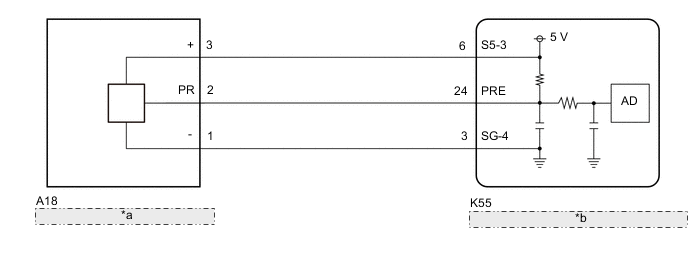
| *a | Air Conditioner Pressure Sensor |
| *b | Air Conditioning Amplifier Assembly |
PROCEDURE
-
CHECK REFRIGERANT PRESSURE
-
Connect the GTS to the DLC3.
-
Turn the ignition switch to ON.
-
Turn the GTS on.
-
Enter the following menus: Body Electrical / Air Conditioner / Data List.
-
Read the Data List according to the display on the GTS.
Body Electrical > Air Conditioner > Data ListTester Display Measurement Item Range Normal Condition Diagnostic Note Regulator Pressure Sensor Air conditioner pressure sensor Min.: -456.6 kPaG (gauge)
Max.: 3294.3 kPaG (gauge)
Actual refrigerant pressure displayed
-
Refrigerant line (gas leak etc.)
-
Air conditioner pressure sensor circuit malfunction
Body Electrical > Air Conditioner > Data ListTester Display Regulator Pressure Sensor -
-
Install a manifold gauge set.
-
Read the manifold gauge set with the following conditions met.
Measurement Condition: Item Condition Vehicle doors Fully open Temperature setting MAX COLD Blower speed HI A/C switch On Recirculation/fresh switch RECIRCULATION Interior temperature 30 to 35°C (86 to 95°F) Standard Pressure Low pressure side 150 to 250 kPa (1.5 to 2.5 kgf/cm2, 22 to 36 psi) High pressure side 1370 to 1570 kPa (14 to 16 kgf/cm2, 199 to 228 psi) -
Compare the values displayed in the Data List and on the manifold gauge set.
OK The values displayed in the Data List and on the manifold gauge set match. Result Proceed to OK NG
OK 
INSPECT REFRIGERANT PRESSURE WITH MANIFOLD GAUGE SET Click here
NG 
-
-
CHECK HARNESS AND CONNECTOR (POWER SOURCE CIRCUIT)
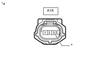
*a Front view of wire harness connector
(to Air Conditioner Pressure Sensor)
-
Disconnect the A18 air conditioner pressure sensor connector.
-
Measure the voltage according to the value(s) in the table below.
Standard Voltage Tester Connection Condition Specified Condition A18-3 (+) - Body ground Ignition switch ON 4.75 to 5.25 V Result Proceed to OK NG
NG 
CHECK HARNESS AND CONNECTOR (AIR CONDITIONER PRESSURE SENSOR - AIR CONDITIONING AMPLIFIER ASSEMBLY) Click here
OK
-
-
CHECK HARNESS AND CONNECTOR (AIR CONDITIONER PRESSURE SENSOR - BODY GROUND)
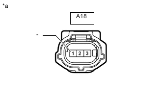
*a Front view of wire harness connector
(to Air Conditioner Pressure Sensor)
-
Measure the resistance according to the value(s) in the table below.
Standard Resistance Tester Connection Condition Specified Condition A18-1 (-) - Body ground Always Below 1 Ω Result Proceed to OK NG
NG
CHECK HARNESS AND CONNECTOR (AIR CONDITIONER PRESSURE SENSOR - AIR CONDITIONING AMPLIFIER ASSEMBLY) Click here
OK
-
-
CHECK HARNESS AND CONNECTOR (AIR CONDITIONER PRESSURE SENSOR - AIR CONDITIONING AMPLIFIER ASSEMBLY)
-
Disconnect the K55 air conditioning amplifier assembly connector.
-
Measure the resistance according to the value(s) in the table below.
Standard Resistance Tester Connection Condition Specified Condition A18-2 (PR) - K55-24 (PRE) Always Below 1 Ω A18-2 (PR) or K55-24 (PRE) - Other terminals and body ground Always 10 kΩ or higher Result Proceed to OK NG
NG
REPAIR OR REPLACE HARNESS OR CONNECTOR
OK
-
-
INSPECT AIR CONDITIONER PRESSURE SENSOR (SENSOR SIGNAL CIRCUIT)
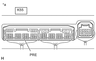
*a Component with harness connected
(Air Conditioning Amplifier Assembly)
-
Measure the voltage with the following conditions met.
Measurement Condition: Item Condition Vehicle doors Fully open Temperature setting MAX COLD Blower speed HI A/C switch On Recirculation/fresh switch RECIRCULATION Interior temperature 25 to 35°C (77 to 95°F) Note
-
If refrigerant pressure on the high pressure side becomes extremely high during the inspection (if the voltage exceeds 4.61 V), a fail-safe function will stop compressor operation. In this case, make sure to measure the voltage before the fail-safe function operates.
-
It is necessary to measure the voltage for a certain amount of time (approximately 10 minutes) because the malfunction may recur after a while.
Tech Tips
When the ambient air temperature is low (below -1.5°C (29.3°F)), the compressor with pulley will be stopped, due to inputs of the thermistor assembly and No. 1 cooler thermistor, to prevent the evaporator from freezing. In this case, perform the inspection in a warm indoor environment.
-
Measure the voltage according to the value(s) in the table below.
Standard Voltage Tester Connection Condition Specified Condition K55-24 (PRE) - Body ground Ignition switch ON
(A/C switch: On)
0.74 to 4.61 V
-
-
Connect the GTS to the DLC3.
-
Turn the ignition switch to ON.
-
Turn the GTS on.
-
Enter the following menus: Body Electrical / Air Conditioner / Data List.
-
Read the Data List according to the display on the GTS.
Body Electrical > Air Conditioner > Data ListTester Display Measurement Item Range Normal Condition Diagnostic Note Regulator Pressure Sensor Air conditioner pressure sensor Min.: -456.6 kPaG (gauge)
Max.: 3294.3 kPaG (gauge)
Actual refrigerant pressure displayed
-
Refrigerant line (gas leak etc.)
-
Air conditioner pressure sensor circuit malfunction
Body Electrical > Air Conditioner > Data ListTester Display Regulator Pressure Sensor OK The voltage and value displayed in the Data List change. Result Result Proceed to OK A NG (The voltage changes but the value displayed in the Data List does not change.) NG (The voltage does not change.) B -
A
REPLACE AIR CONDITIONING AMPLIFIER ASSEMBLY Click here
B
REPLACE AIR CONDITIONER PRESSURE SENSOR Click here
-
-
CHECK HARNESS AND CONNECTOR (AIR CONDITIONER PRESSURE SENSOR - AIR CONDITIONING AMPLIFIER ASSEMBLY)
-
Disconnect the K55 air conditioning amplifier assembly connector.
-
Measure the resistance according to the value(s) in the table below.
Standard Resistance Tester Connection Condition Specified Condition A18-1 (-) - K55-3 (SG-4) Always Below 1 Ω A18-1 (-) or K55-3 (SG-4) - Other terminals and body ground Always 10 kΩ or higher Result Proceed to OK NG
OK
REPLACE AIR CONDITIONING AMPLIFIER ASSEMBLY Click here
NG
REPAIR OR REPLACE HARNESS OR CONNECTOR
-
-
CHECK HARNESS AND CONNECTOR (AIR CONDITIONER PRESSURE SENSOR - AIR CONDITIONING AMPLIFIER ASSEMBLY)
-
Disconnect the K55 air conditioning amplifier assembly connector.
-
Measure the resistance according to the value(s) in the table below.
Standard Resistance Tester Connection Condition Specified Condition A18-3 (+) - K55-6 (S5-3) Always Below 1 Ω A18-3 (+) or K55-6 (S5-3) - Other terminals and body ground Always 10 kΩ or higher Result Proceed to OK NG
OK
REPLACE AIR CONDITIONING AMPLIFIER ASSEMBLY Click here
NG
REPAIR OR REPLACE HARNESS OR CONNECTOR
-