AIR CONDITIONING SYSTEM(for Automatic Air Conditioning System) TERMINALS OF ECU
-
CHECK AIR CONDITIONING AMPLIFIER ASSEMBLY
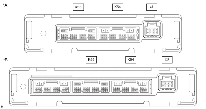
*A w/o Seat Heater *B w/ Seat Heater Tech Tips
Check from the rear of the connector while it is connected to the air conditioning amplifier assembly.
Terminal No.
(Symbol)
Wiring Color Terminal Description Condition Specified Condition K55-1 (SG-1) - Body ground LG - Body ground Ground for cooler (room temp. sensor) thermistor Always Below 1 V K55-2 (SG-2) - Body ground W - Body ground Ground for thermistor assembly Always Below 1 V K55-3 (SG-4) - Body ground L - Body ground Ground for air conditioner pressure sensor Always Below 1 V K55-6 (S5-3) - K55-3 (SG-4) GR - L Power supply for air conditioner pressure sensor Ignition switch ON 4.75 to 5.25 V Ignition switch off Below 1 V K55-9 (MGC) - K54-4 (GND)*1 G - W-B Magnetic clutch operation signal
-
Engine running
-
Blower switch: LO
-
A/C switch: Off
11 to 14 V
-
Engine running
-
Blower switch: LO
-
A/C switch: On
Below 1 V K55-13 (TAM) - K55-2 (SG-2) R - W Thermistor assembly signal
-
Ignition switch ON
-
Ambient temperature: 25°C (77°F)
1.05 to 1.45 V
-
Ignition switch ON
-
Ambient temperature: 40°C (104°F)
0.64 to 0.87 V K55-14 (TR) - K55-1 (SG-1) GR - LG Cooler (room temp. sensor) thermistor signal
-
Ignition switch ON
-
Cabin temperature: 25°C (77°F)
1.8 to 2.2 V
-
Ignition switch ON
-
Cabin temperature: 40°C (104°F)
1.2 to 1.6 V K55-20 (ECOS) - K54-4 (GND)*2 W - W-B ECO switch assembly (electric parking brake switch assembly) signal
-
Ignition switch ON
-
ECO switch assembly (electric parking brake switch assembly): Off
11 to 14 V
-
Ignition switch ON
-
ECO switch assembly (electric parking brake switch assembly): On
Below 1 V K55-21 (LOCK) - K55-2 (SG-2)*1 B - W A/C lock sensor signal
-
Engine running
-
Blower switch: LO
-
A/C switch: On
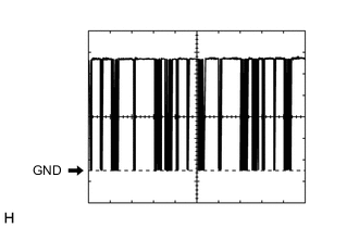
Pulse generation
(See waveform 1)
K55-24 (PRE) - K55-3 (SG-4) W - L Air conditioner pressure sensor signal
-
Engine running
-
Air conditioning system operating
-
Refrigerant pressure: Abnormal pressure (more than 3025 kPa (30.8 kgf/cm2, 439 psi))
4.61 V or higher
-
Engine running
-
Air conditioning system operating
-
Refrigerant pressure: Abnormal pressure (less than 176 kPa (1.8 kgf/cm2, 26 psi))
Below 0.74 V
-
Engine running
-
Air conditioning system operating
-
Refrigerant pressure: Normal pressure (less than 3025 kPa (30.8 kgf/cm2, 439 psi) and more than 176 kPa (1.8 kgf/cm2, 26 psi))
0.74 to 4.61 V K54-1 (B) - K54-4 (GND) LA-B - W-B Power source (Back-up) Always 11 to 14 V K54-2 (IG+) - K54-4 (GND) LA-GR - W-B Power source (IG) Ignition switch ON 11 to 14 V Ignition switch off Below 1 V K54-3 (SOL+) - K54-4 (GND) R - W-B Compressor solenoid operation signal
-
Engine running
-
Blower switch: LO
-
A/C switch: On
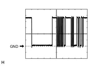
Pulse generation
(See waveform 2)
K54-4 (GND) - Body ground W-B - Body ground Ground for main power supply Always Below 1 V K54-6 (BLW) - K54-4 (GND) LG - W-B Blower motor speed control signal
-
Ignition switch ON
-
Blower switch: LO
Pulse generation
(See waveform 3)
K54-7 (NANO) - K54-4 (GND)*3 LG - W-B Ion generator sub-assembly operation signal
-
Ignition switch ON
-
Blower switch: On
Below 1 V
-
Ignition switch ON
-
Blower switch: Off
4.75 to 5.25 V K54-11 (CANH) - K54-12 (CANL) SB - W CAN communication system CAN communication is performed Pulse generation K54-14 (LIN1) - K54-4 (GND) BE - W-B LIN communication signal Ignition switch ON Pulse generation
(See waveform 4)
K54-26 (NAIN) - K54-4 (GND)*3 BE - W-B Ion generator sub-assembly operation condition signal
-
Ignition switch ON
-
Blower switch: On
Below 2.2 V
-
Ignition switch ON
-
Blower switch: Off
4.75 to 5.25 V z8-2 (BUS G) - Body ground - Ground for BUS IC Always Below 1 V z8-3 (BUS) - z8-2 (BUS G) - BUS IC control signal Ignition switch ON Pulse generation
(See waveform 5)
z8-4 (B BUS) - z8-2 (BUS G) - Power supply for BUS IC Ignition switch off 11 to 14 V z8-5 (SG) - Body ground GR - Body ground Ground for No. 1 cooler thermistor Always Below 1 V z8-6 (TE) - z8-5 (SG) GR - GR No. 1 cooler thermistor signal
-
Ignition switch ON
-
Evaporator temperature: 0°C (32°F)
1.7 to 2.1 V
-
Ignition switch ON
-
Evaporator temperature: 15°C (59°F)
0.9 to 1.3 V
-
*1: for 2GR-FKS
-
*2: w/ ECO Switch
-
*3: w/ Ion Generator
-
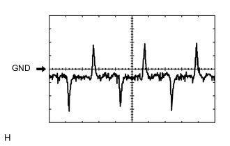
Waveform 1:
Item Content Terminal No. K55-21 (LOCK) - K55-2 (SG-2) Tool Setting 200 mV/DIV., 10 ms./DIV. Condition
-
Engine running
-
Blower switch: LO
-
A/C switch: On
-
-
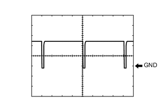
Waveform 2:
Item Content Terminal No. K54-3 (SOL+) - K54-4 (GND) Tool Setting 5 V/DIV., 500 μs./DIV. Condition
-
Engine running
-
Blower switch: LO
-
A/C switch: On
-
-
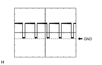
Waveform 3:
Item Content Terminal No. K54-6 (BLW) - K54-4 (GND) Tool Setting 2 V/DIV., 1 ms./DIV. Condition
-
Ignition switch ON
-
Blower switch: LO
-
-
Waveform 4:
Item Content Terminal No. K54-14 (LIN1) - K54-4 (GND) Tool Setting 2 V/DIV., 20 ms./DIV. Condition Ignition switch ON -
Waveform 5:
Item Content Terminal No. z8-3 (BUS) - z8-2 (BUS G) Tool Setting 2 V/DIV., 2 ms./DIV. Condition Ignition switch ON
-
-
CHECK AIR CONDITIONING CONTROL PANEL (RADIO AND DISPLAY RECEIVER ASSEMBLY) (w/ Radio and Display Receiver)

Tech Tips
Check from the rear of the connector while it is connected to the air conditioning control panel (radio and display receiver assembly).
Terminal No.
(Symbol)
Wiring Color Terminal Description Condition Specified Condition h1-2 (IG+) - h1-6 (GND) SB - W-B Power source (IG) Ignition switch off Below 1 V Ignition switch ON 11 to 14 V h1-3 (+B) - h1-6 (GND) G - W-B Power source (Back-up) Ignition switch off 11 to 14 V h1-6 (GND) - Body ground W-B - Body ground Ground for air conditioning control panel (radio and display receiver assembly) Always Below 1 V h1-11 (ILL+) - Body ground W - Body ground Illumination signal Light control switch in off position Below 1 V Light control switch in tail or head position 11 to 14 V h1-15 (ILL-) - Body ground L - Body ground Illumination signal Always Below 1 V -
CHECK AIR CONDITIONING CONTROL ASSEMBLY (w/o Radio and Display Receiver)

Tech Tips
Check from the rear of the connector while it is connected to the air conditioning control assembly.
Terminal No.
(Symbol)
Wiring Color Terminal Description Condition Specified Condition K26-2 (IG+) - K26-6 (GND) GR - W-B Power source (IG) Ignition switch off Below 1 V Ignition switch ON 11 to 14 V K26-6 (GND) - Body ground W-B - Body ground Ground for air conditioning control assembly Always Below 1 V K26-9 (LIN1) - Body ground LG - Body ground LIN communication signal Ignition switch ON Pulse generation
(See waveform)
K26-11 (ILL+) - Body ground W - Body ground Illumination signal Light control switch in off position Below 1 V Light control switch in tail or head position 11 to 14 V K26-15 (ILL-) - Body ground B - Body ground Illumination signal Always Below 1 V
-
Waveform:
Item Content Terminal No. K26-9 (LIN1) - Body ground Tool Setting 2 V/DIV., 20 ms./DIV. Condition Ignition switch ON
-
-
COOLER CONTROL SWITCH ASSEMBLY (for 3 Zone Type)
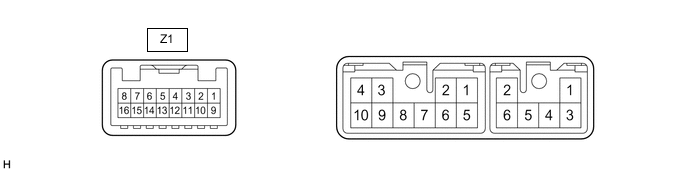
Terminal No.
(Symbol)
Wiring Color Terminal Description Condition Specified Condition Z1-1 (ACC) - Z1-16 (GND) GR - W-B Power source (ACC) Ignition switch off Below 1 V Ignition switch ACC 11 to 14 V Z1-9 (+B) - Z1-16 (GND) R - W-B Power source (+B) Always 11 to 14 V Z1-10 (IG+) - Z1-16 (GND) L - W-B Power source (IG) Ignition switch off Below 1 V Ignition switch ON 11 to 14 V Z1-11 (ILL+) - Body ground G - Body ground Illumination signal Light control switch in off position Below 1 V Light control switch in tail or head position 11 to 14 V Z1-13 (RLIN) - Body ground L - Body ground LIN communication signal Ignition switch ON Pulse generation
(See waveform)
Z1-16 (GND) - Body ground W-B - Body ground Ground Always Below 1 V
-
Waveform:
Item Content Terminal No. Z1-13 (RLIN) - Body ground Tool Setting 2 V/DIV., 20 ms./DIV. Condition Ignition switch ON
-