| DTC Code | DTC Name |
|---|---|
| ECU Power Source Circuit |
DESCRIPTION
This circuit supplies power to the millimeter wave radar sensor assembly when the ignition switch is ON.
WIRING DIAGRAM
CAUTION / NOTICE / HINT
Inspect the fuses for circuits related to this system before performing the following inspection procedure.
PROCEDURE
- Click here
CHECK MILLIMETER WAVE RADAR SENSOR ASSEMBLY (B VOLTAGE)
-
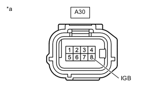
*a Front view of wire harness connector
(to Millimeter Wave Radar Sensor Assembly)
Disconnect the A30 millimeter wave radar sensor assembly connector.
-
Turn the ignition switch to ON.
-
Measure the voltage according to the value(s) in the table below.
Standard Voltage Tester Connection Condition Specified Condition A30-8 (IGB) - Body ground Ignition switch ON 11 to 14 V -
Turn the ignition switch off.
-
Connect the A30 millimeter wave radar sensor assembly connector.
Result Proceed to OK NG
- OKClick here
- NG
REPAIR OR REPLACE HARNESS OR CONNECTOR (POWER SOURCE CIRCUIT)
-
- Click here
CHECK HARNESS AND CONNECTOR (MILLIMETER WAVE RADAR SENSOR ASSEMBLY - BODY GROUND)
-
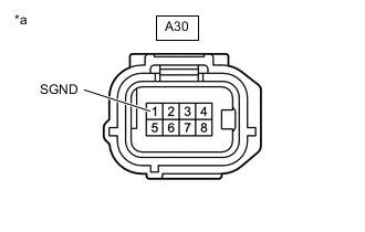
*a Front view of wire harness connector
(to Millimeter Wave Radar Sensor Assembly)
Disconnect the A30 millimeter wave radar sensor assembly connector.
-
Measure the resistance according to the value(s) in the table below.
Standard Resistance Tester Connection Condition Specified Condition A30-1 (SGND) - Body ground Always Below 1 Ω -
Connect the A30 millimeter wave radar sensor assembly connector.
Result Proceed to OK NG
- OK
PROCEED TO NEXT SUSPECTED AREA SHOWN IN PROBLEM SYMPTOMS TABLEClick here
- NG
REPAIR OR REPLACE HARNESS OR CONNECTOR
-