SPIRAL CABLE REMOVAL
CAUTION / NOTICE / HINT
The necessary procedures (adjustment, calibration, initialization or registration) that must be performed after parts are removed and installed, or replaced during spiral cable sub-assembly removal/installation are shown below.
| Replaced Part or Performed Procedure | Necessary Procedure | Effect/Inoperative Function when Necessary Procedure not Performed | Link |
|---|---|---|---|
| Removal/installation of the spiral cable with sensor sub-assembly |
|
Parking assist monitor system | Click here for Initialization Click here for Calibration |
| Disconnect cable from negative battery terminal | Perform steering sensor zero point calibration | Lane departure alert system (w/ Steering Control) | |
| Pre-collision system | |||
| Memorize steering angle neutral point | Parking assist monitor system |
PROCEDURE
-
PRECAUTION
Note
After turning the ignition switch off, waiting time may be required before disconnecting the cable from the negative (-) battery terminal. Therefore, make sure to read the disconnecting the cable from the negative (-) battery terminal notices before proceeding with work.
-
CHANGE POWER TILT AND POWER TELESCOPIC STEERING COLUMN SYSTEM SETTINGS (for Power Tilt and Power Telescopic Steering Column)
-
ALIGN FRONT WHEELS FACING STRAIGHT AHEAD
-
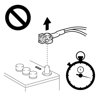
DISCONNECT CABLE FROM NEGATIVE BATTERY TERMINAL
for 2AR-FE: Click here
for A25A-FKS: Click here
for 2GR-FKS: Click here
CAUTION:
Wait at least 90 seconds after disconnecting the cable from the negative (-) battery terminal to disable the SRS system.
Note
When disconnecting the cable, some systems need to be initialized after the cable is reconnected.
-
REMOVE LOWER NO. 2 STEERING WHEEL COVER
-
REMOVE HORN BUTTON ASSEMBLY
-
REMOVE STEERING WHEEL ASSEMBLY
-
REMOVE LOWER STEERING COLUMN COVER SUB-ASSEMBLY (for Manual Tilt and Manual Telescopic Steering Column)
-
REMOVE LOWER STEERING COLUMN COVER SUB-ASSEMBLY (for Power Tilt and Power Telescopic Steering Column)
-
REMOVE UPPER STEERING COLUMN COVER (for Manual Tilt and Manual Telescopic Steering Column)
-
REMOVE UPPER STEERING COLUMN COVER (for Power Tilt and Power Telescopic Steering Column)
-
REMOVE SPIRAL CABLE WITH SENSOR SUB-ASSEMBLY
Note
-
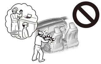
Do not remove/install the spiral cable with sensor sub-assembly with the battery connected and the ignition switch ON.
-
Do not rotate the spiral cable with sensor sub-assembly without the steering wheel assembly installed, with the battery connected and the ignition switch ON.
-
Ensure that the steering wheel assembly is installed and aligned straight when inspecting the steering sensor.
-
Check that the ignition switch is off.
-
Check that the cable is disconnected from the negative (-) battery terminal.
CAUTION:
Wait at least 90 seconds after disconnecting the cable from the negative (-) battery terminal to disable the SRS system.
-
Check that the front wheels are aligned facing straight ahead.
-
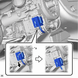
*a Slider 
Release in this Direction Slide the slider to release the lock, and then disconnect the yellow airbag connector from the spiral cable with sensor sub-assembly.
Note
When disconnecting any airbag connector, take care not to damage the airbag wire harness.
-
Disconnect the other connectors from the spiral cable with sensor sub-assembly.
-
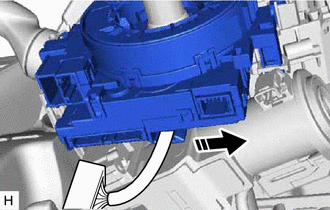
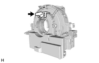
Separate in this Direction Separate the wire harness from the spiral cable with sensor sub-assembly as shown in the illustration.
-
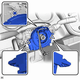
Disengage the claw and 2 clips to remove the spiral cable with sensor sub-assembly.
-
-
REMOVE SPIRAL CABLE SUB-ASSEMBLY
Note
-
Remove the steering sensor from the spiral cable sub-assembly only when replacing the spiral cable sub-assembly or the steering sensor.
-
Removing the steering sensor from the spiral cable sub-assembly without using a lock pin may result in the center position of the steering sensor becoming misaligned. Therefore, make sure to use the lock pin provided with a new spiral cable sub-assembly when removing the steering sensor from the spiral cable sub-assembly.
-
When replacing the steering sensor:
-
Install the lock pin to the steering sensor.
Note
-
Use the lock pin provided with a new spiral cable sub-assembly.
-
Do not remove the lock pin before installing the steering sensor to the spiral cable sub-assembly.
-
-
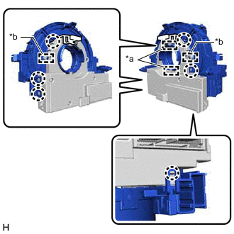
*a Guide *b Pin Disengage the 6 claws and 2 pins to remove the spiral cable sub-assembly from the steering sensor.
Note
Do not damage the pins of the spiral cable sub-assembly or guides of the steering sensor.
-