| DTC Code | DTC Name |
|---|---|
| B1782 | Rear Occupant Classification Sensor LH Circuit Malfunction |
DESCRIPTION
The rear occupant classification sensor LH circuit consists of the occupant detection ECU and rear occupant classification sensor LH.
DTC B1782 is stored when a malfunction is detected in the rear occupant classification sensor LH circuit.
| DTC No. | Detection Item | DTC Detection Condition | Trouble Area |
|---|---|---|---|
| B1782 | Rear Occupant Classification Sensor LH Circuit Malfunction |
|
|
-
*: The rear occupant classification sensor LH is built into the front seat adjuster assembly RH.
CAUTION / NOTICE / HINT
After turning the ignition switch off, waiting time may be required before disconnecting the cable from the negative (-) battery terminal. Therefore, make sure to read the disconnecting the cable from the negative (-) battery terminal notices before proceeding with work.
-
When DTC B1650 is stored as a result of troubleshooting for the airbag system, check the DTCs stored in the occupant detection ECU. When DTC B1782 is output, perform troubleshooting for this DTC first.
-
If it is difficult to perform troubleshooting (wire harness inspection), remove the front passenger seat installation bolts to see under the seat cushion.
-
In the above case, lift and hold the seat so that it does not fall down. Hold the seat only as necessary because holding the seat for a long period of time may cause seat rail deformation.
PROCEDURE
- Click here
CHECK CONNECTORS
-
Turn the ignition switch off.
-
Disconnect the cable from the negative (-) battery terminal.
-
Check that the connectors are properly connected to the occupant detection ECU and rear occupant classification sensor LH.
OK The connectors are properly connected. Tip:If the connectors are not properly connected, reconnect the connectors and proceed to the next inspection.
-
Disconnect the connectors from the occupant detection ECU and rear occupant classification sensor LH.
-
Check that the terminals of the connectors are not deformed or damaged.
OK The terminals are not deformed or damaged. Result Proceed to OK NG
- OKClick here
- NG
REPLACE FRONT SEAT WIRE RH
-
- Click here
CHECK FRONT SEAT WIRE RH
-
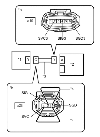
*1 Rear Occupant Classification Sensor LH *2 Occupant Detection ECU *3 Front Seat Wire RH *4 Service Wire *a Front view of wire harness connector
(to Occupant Detection ECU)
*b Front view of wire harness connector
(to Rear Occupant Classification Sensor LH)
Connect the cable to the negative (-) battery terminal.
-
Turn the ignition switch to ON.
-
Measure the voltage according to the value(s) in the table below.
Standard Voltage Tester Connection Condition Specified Condition a19-2 (SVC3) - Body ground Ignition switch ON Below 1 V a19-4 (SIG3) - Body ground Ignition switch ON Below 1 V a19-6 (SGD3) - Body ground Ignition switch ON Below 1 V -
Turn the ignition switch off.
-
Disconnect the cable from the negative (-) battery terminal.
-
Using service wires, connect terminals 1 (SVC) and 3 (SGD), and terminals 2 (SIG) and 3 (SGD) of connector C.
Note:Do not forcibly insert the service wire into the terminals of the connector when connecting the wire.
-
Measure the resistance according to the value(s) in the table below.
Standard Resistance Tester Connection Condition Specified Condition a19-2 (SVC3) - a19-6 (SGD3) Always Below 1 Ω a19-4 (SIG3) - a19-6 (SGD3) Always Below 1 Ω -
Disconnect the service wires from connector C.
-
Measure the resistance according to the value(s) in the table below.
Standard Resistance Tester Connection Condition Specified Condition a19-2 (SVC3) - a19-6 (SGD3) Always 1 MΩ or higher a19-4 (SIG3) - a19-6 (SGD3) Always 1 MΩ or higher a19-2 (SVC3) - a19-4 (SIG3) Always 1 MΩ or higher a19-2 (SVC3) - Body ground Always 1 MΩ or higher a19-4 (SIG3) - Body ground Always 1 MΩ or higher a19-6 (SGD3) - Body ground Always 1 MΩ or higher Result Proceed to OK NG
- OKClick here
- NG
REPLACE FRONT SEAT WIRE RH
-
- Click here
CHECK DTC
-
Connect the connectors to the occupant detection ECU and rear occupant classification sensor LH.
-
Connect the cable to the negative (-) battery terminal.
-
Turn the ignition switch to ON, and wait for at least 60 seconds.
-
Clear the DTCs stored in the occupant detection ECU.
- Body Electrical > Occupant Detection > Clear DTCs
-
-
-
Clear the DTCs stored in the airbag sensor assembly.
- Body Electrical > SRS Airbag > Clear DTCs
-
-
-
Turn the ignition switch off.
-
Turn the ignition switch to ON, and wait for at least 10 seconds.
-
Check for DTCs.
- Body Electrical > Occupant Detection > Trouble Codes
-
-
OK DTC B1782 is not output. Tip:Codes other than DTC B1782 may be output at this time, but they are not related to this check.
-
Turn the ignition switch off.
Result Proceed to OK NG
- OK
USE SIMULATION METHOD TO CHECKClick here
- NGClick here
-
- Click here
CHECK OCCUPANT DETECTION ECU
-
Disconnect the cable from the negative (-) battery terminal.
-
Replace the occupant detection ECU with a known good one.
Tip:Perform the following inspection using known good parts from another vehicle if possible.
-
Connect the cable to the negative (-) battery terminal.
-
Turn the ignition switch to ON, and wait for at least 60 seconds.
-
Clear the DTCs stored in the occupant detection ECU.
- Body Electrical > Occupant Detection > Clear DTCs
-
-
-
Clear the DTCs stored in the airbag sensor assembly.
- Body Electrical > SRS Airbag > Clear DTCs
-
-
-
Turn the ignition switch off.
-
Turn the ignition switch to ON, and wait for at least 10 seconds.
-
Check for DTCs.
- Body Electrical > Occupant Detection > Trouble Codes
-
-
OK DTC B1782 is not output. Tip:Codes other than DTC B1782 may be output at this time, but they are not related to this check.
-
Turn the ignition switch off.
-
Disconnect the cable from the negative (-) battery terminal.
-
Restore the occupant detection ECU that was installed for testing to its original location.
Result Proceed to OK NG
- OKClick here
- NGClick here
-
- Click here
REPLACE OCCUPANT DETECTION ECU
-
Turn the ignition switch off.
-
Disconnect the cable from the negative (-) battery terminal.
-
Replace the occupant detection ECU with a new one.
-
Connect the cable to the negative (-) battery terminal.
Result Proceed to NEXT
- NEXTClick here
-
- Click here
PERFORM ZERO POINT CALIBRATION
-
Using the GTS, perform Zero Point Calibration.
Result Proceed to NEXT
- NEXT
END
-
- Click here
REPLACE FRONT SEAT ADJUSTER ASSEMBLY RH
-
Turn the ignition switch off.
-
Disconnect the cable from the negative (-) battery terminal.
-
Replace the front seat adjuster assembly RH.
-
Connect the cable to the negative (-) battery terminal.
Result Proceed to NEXT
- NEXTClick here
-
- Click here
PERFORM ZERO POINT CALIBRATION
-
Using the GTS, perform Zero Point Calibration.
Result Proceed to NEXT
- NEXT
END
-