CENTER AIRBAG SENSOR ASSEMBLY REMOVAL
CAUTION / NOTICE / HINT
The necessary procedures (adjustment, calibration, initialization or registration) that must be performed after parts are removed and installed, or replaced during airbag sensor assembly removal/installation are shown below.
| Replaced Part or Performed Procedure | Necessary Procedure | Effect/Inoperative Function when Necessary Procedure not Performed | Link |
|---|---|---|---|
| Replacement of the airbag sensor assembly | Perform system variant learning and acceleration sensor zero point calibration. |
|
|
| Removal/installation of the front passenger seat*1 | Zero point calibration (Occupant classification system) |
|
|
| Disconnect cable from negative battery terminal | Perform steering sensor zero point calibration | Lane departure alert system (w/ Steering Control) | |
| Pre-collision system | |||
| Memorize steering angle neutral point | Parking assist monitor system |
Tech Tips
-
Use the same procedure for RHD and LHD vehicles.
-
The following procedure is for an LHD vehicle.
PROCEDURE
-
PRECAUTION
Note
After turning the ignition switch off, waiting time may be required before disconnecting the cable from the negative (-) battery terminal. Therefore, make sure to read the disconnecting the cable from the negative (-) battery terminal notices before proceeding with work.
-
REMOVE FRONT SEAT ASSEMBLY (for Power Seat)
-
REMOVE FRONT SEAT ASSEMBLY (for Manual Seat)
-
REMOVE CONSOLE BOX ASSEMBLY
-
DISCONNECT REAR CENTER SEAT OUTER BELT ASSEMBLY
for Fold Down Seat Type: Click here
for Reclining Seat Type: Click here
for Fixed Seat Type: Click here
-
REMOVE REAR SEAT CUSHION ASSEMBLY
for Fold Down Seat Type: Click here
for Reclining Seat Type: Click here
for Fixed Seat Type: Click here
-
REMOVE REAR SEAT CUSHION LOCK HOOK
for Fold Down Seat Type: Click here
for Reclining Seat Type: Click here
for Fixed Seat Type: Click here
-
REMOVE FRONT DOOR SCUFF PLATE LH
-
REMOVE COWL SIDE TRIM SUB-ASSEMBLY LH
-
DISCONNECT FRONT DOOR OPENING TRIM WEATHERSTRIP LH
Tech Tips
Disconnect the front door opening trim weatherstrip LH to the extent that allows the removal of the lower center pillar garnish LH.
-
REMOVE REAR DOOR SCUFF PLATE LH
-
DISCONNECT REAR DOOR OPENING TRIM WEATHERSTRIP LH
Tech Tips
Disconnect the rear door opening trim weatherstrip LH to the extent that allows the removal of the lower center pillar garnish LH.
-
REMOVE LOWER CENTER PILLAR GARNISH LH
-
REMOVE NO. 1 INSTRUMENT PANEL UNDER COVER SUB-ASSEMBLY (for LHD)
-
REMOVE NO. 1 INSTRUMENT PANEL UNDER COVER SUB-ASSEMBLY (for RHD)
-
REMOVE FRONT DOOR SCUFF PLATE RH
-
REMOVE COWL SIDE TRIM SUB-ASSEMBLY RH
-
DISCONNECT FRONT DOOR OPENING TRIM WEATHERSTRIP RH
Tech Tips
Disconnect the front door opening trim weatherstrip RH to the extent that allows the removal of the lower center pillar garnish RH.
-
REMOVE REAR DOOR SCUFF PLATE RH
-
DISCONNECT REAR DOOR OPENING TRIM WEATHERSTRIP RH
Tech Tips
Disconnect the rear door opening trim weatherstrip RH to the extent that allows the removal of the lower center pillar garnish RH.
-
REMOVE LOWER CENTER PILLAR GARNISH RH
-
REMOVE NO. 2 INSTRUMENT PANEL UNDER COVER SUB-ASSEMBLY
-
REMOVE ACCELERATOR PEDAL PAD
for 2AR-FE: Click here
for A25A-FKS: Click here
for 2GR-FKS: Click here
-
REMOVE ACCELERATOR PEDAL
for 2AR-FE: Click here
for A25A-FKS: Click here
for 2GR-FKS: Click here
-
REMOVE FRONT FLOOR CAUTION PLATE COVER
-
DISCONNECT FRONT FLOOR CARPET ASSEMBLY
-
for LHD:
-
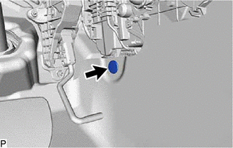
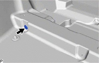
Remove the front floor carpet clip.
-
-
Remove the front floor carpet clip.
-
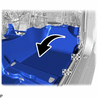
Disengage the 2 guides and turn back the front floor carpet assembly as shown in the illustration.
-
Remove the front floor carpet clip.
-
Remove the front floor carpet clip.
-
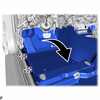
Disengage the 2 guides and turn back the front floor carpet assembly as shown in the illustration.
-
-
REMOVE NO. 1 CONSOLE BOX DUCT
-
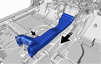

Remove in this Direction Remove the clip.
-
Remove the No. 1 console box duct as shown in the illustration.
-
-
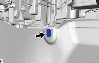
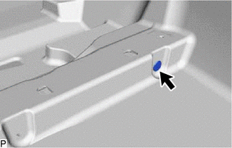
REMOVE AIRBAG SENSOR ASSEMBLY
-
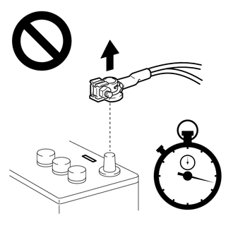
Check that the ignition switch is off.
-
Check that the cable is disconnected from the negative (-) battery terminal.
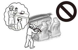
CAUTION:
Wait at least 90 seconds after disconnecting the cable from the negative (-) battery terminal to disable the SRS system.
-
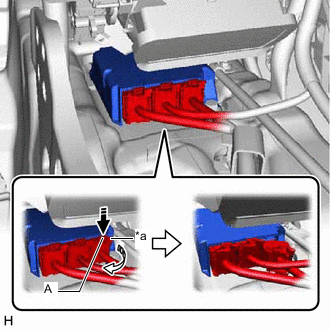
*a Lock Lever Release the lock (1) 
Disconnect the connector (2) Push down the part (A) in the direction indicated by the arrow (1) to release the lock, and then move the lock lever in the direction indicated by the arrow (2) shown in the illustration to disconnect the connectors.
Note
When disconnecting any airbag connector, take care not to damage the airbag wire harness.
-
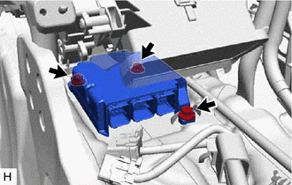
Remove the 3 bolts and airbag sensor assembly.
-