HEADUP DISPLAY REASSEMBLY
PROCEDURE
-
INSTALL NO. 1 COMBINATION METER MIRROR PLATE
-
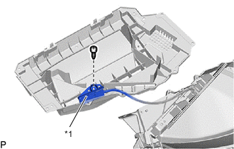
*1 Light Sensor Assembly Connect the light sensor assembly with the screw.
-
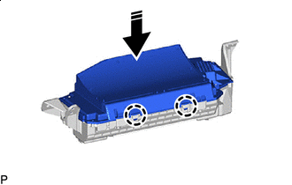

Install in this Direction Engage the 2 claws as shown in the illustration.
-
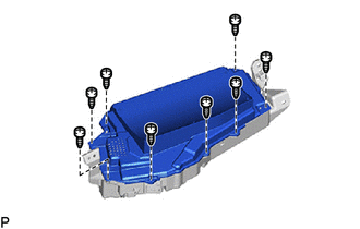
Install the No. 1 combination meter mirror plate with the 8 screws.
-
-
INSTALL COMBINATION SPEED METER CUSHION
-
Clean the meter mirror sub-assembly surface.
-
Remove any remaining double-sided tape from the meter mirror sub-assembly.
-
Wipe off any tape adhesive residue with cleaner.
-
-
Remove the release paper from a new combination speed meter cushion.
Tech Tips
After removing the release paper, keep the exposed adhesive free from foreign matter.
-


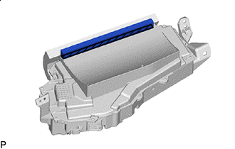
Double-sided Tape Install the combination speed meter cushion.
-
-
INSTALL NO. 1 COMBINATION SPEED METER CUSHION
-
Clean the meter mirror sub-assembly surface.
-
Remove any remaining double-sided tape from the meter mirror sub-assembly.
-
Wipe off any tape adhesive residue with cleaner.
-
-
Remove the release paper from a new No. 1 combination speed meter cushion.
Tech Tips
After removing the release paper, keep the exposed adhesive free from foreign matter.
-
Double-sided Tape Install the No. 1 combination speed meter cushion.
-
-
INSTALL METER MIRROR WIRE
-
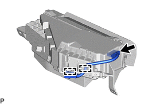
Engage the 2 clamps.
-
Connect the connector to install the meter mirror wire.
-