METER / GAUGE SYSTEM, Diagnostic DTC:B150819
| DTC Code | DTC Name |
|---|---|
| B150819 | Turn Signal/Hazard Flasher Circuit Current Above Threshold |
DESCRIPTION
This DTC is stored when the combination meter assembly detects a short in a turn signal light circuit.
Tech Tips
If there is a short in a turn signal light circuit, all of the turn signal lights in that circuit will not blink.
| DTC No. | Detection Item | DTC Detection Condition | Trouble Area | Memory | Note |
|---|---|---|---|---|---|
| B150819 | Turn Signal/Hazard Flasher Circuit Current Above Threshold | Diagnosis Condition:
Malfunction Status:
|
|
DTC stored | - |
-
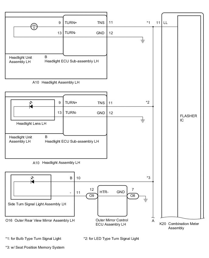
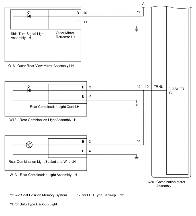
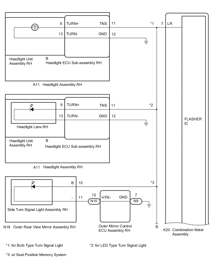
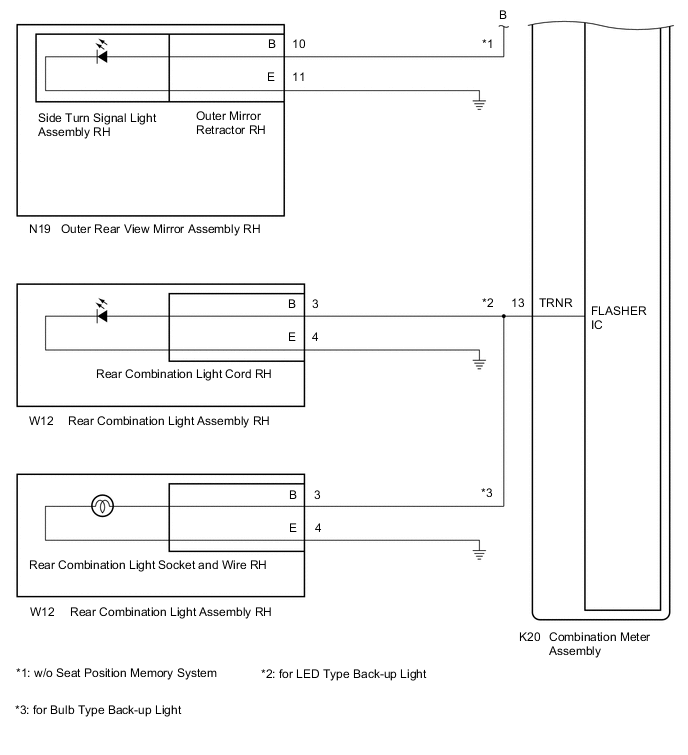
*1: for LED Type Turn Signal Light
-
*2: for LED Type Back-up Light
-
*3: for Bulb Type Back-up Light
-
*4: w/ Seat Position Memory System
-
*5: w/o Seat Position Memory System
WIRING DIAGRAM
-
LH side
-
RH side
CAUTION / NOTICE / HINT
Note
-
When replacing the combination meter assembly, always replace it with a new one. If a combination meter assembly which was installed to another vehicle is used, the information stored in it will not match the information from the vehicle and a DTC may be stored.
-
Inspect the turn signal light bulbs and sockets before performing the following procedure.
PROCEDURE
-
INSPECT LIGHTS
-
Inspect the illumination of each turn signal light.
Result Result Proceed to All LH turn signal lights do not blink A All RH turn signal lights do not blink B
B 
CHECK HEADLIGHT ASSEMBLY RH Click here
A 
-
-
CHECK HEADLIGHT ASSEMBLY LH
-
Disconnect the A10 headlight assembly LH connector.
-
Operate the headlight dimmer switch assembly and check that the LH side turn signal lights other than the headlight turn signal light blink.
Tech Tips
If the LH side turn signal lights blink, the headlight assembly LH is malfunctioning.
Result Result Proceed to LH side turn signal lights blink A LH side turn signal lights do not blink B
B
CHECK OUTER REAR VIEW MIRROR ASSEMBLY LH Click here
A
-
-
CHECK HEADLIGHT ECU SUB-ASSEMBLY LH
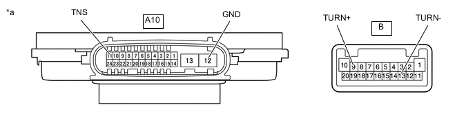
*a Component without harness connected
(Headlight ECU Sub-assembly LH)
- -
-
Remove the headlight ECU sub-assembly LH.
-
Measure the resistance according to the value(s) in the table below.
Standard Resistance Tester Connection Condition Specified Condition B-9 (TURN+) - B-13 (TURN-)
or
A10-11 (TNS) - A10-12 (GND)
Always 10 kΩ or higher Result Proceed to OK NG
NG 
REPLACE HEADLIGHT ECU SUB-ASSEMBLY LH Click here
OK
-
-
CONFIRM MODEL
-
Choose the model to be inspected.
Result Result Proceed to for LED Type Turn Signal Light A for Bulb Type Turn Signal Light B
B
REPLACE HEADLIGHT UNIT ASSEMBLY LH Click here
A
-
-
INSPECT HEADLIGHT LENS LH
-
Remove the headlight lens LH.
-
Inspect the headlight lens LH.
Result Proceed to OK NG
OK
REPLACE HEADLIGHT UNIT ASSEMBLY LH Click here
NG
REPLACE HEADLIGHT LENS LH Click here
-
-
CHECK OUTER REAR VIEW MIRROR ASSEMBLY LH
-
Connect the A10 headlight assembly LH connector.
-
Disconnect the O16 outer rear view mirror assembly LH connector.
-
Operate the headlight dimmer switch assembly and check that the LH side turn signal lights other than the side turn signal light blink.
Tech Tips
If the LH side turn signal lights blink, the outer rear view mirror assembly LH is malfunctioning.
Result Result Proceed to LH side turn signal lights blink A LH side turn signal lights do not blink B
B
CHECK REAR COMBINATION LIGHT ASSEMBLY LH Click here
A
-
-
INSPECT SIDE TURN SIGNAL LIGHT ASSEMBLY LH
-
Remove the side turn signal light assembly LH.
-
Inspect the side turn signal light assembly LH.
Result Proceed to OK NG
NG
REPLACE SIDE TURN SIGNAL LIGHT ASSEMBLY LH Click here
OK
-
-
CONFIRM MODEL
-
Choose the model to be inspected.
Result Result Proceed to w/ Seat Position Memory System A w/o Seat Position Memory System B
A
REPLACE OUTER REAR VIEW MIRROR ASSEMBLY LH Click here
B
REPLACE OUTER MIRROR RETRACTOR LH Click here
-
-
CHECK REAR COMBINATION LIGHT ASSEMBLY LH
-
Connect the O16 outer rear view mirror assembly LH connector.
-
Disconnect the W13 rear combination light assembly LH connector.
-
Operate the headlight dimmer switch assembly and check that the LH side turn signal lights other than the rear turn signal light blink.
Tech Tips
If the LH side turn signal lights blink, the rear combination light assembly LH is malfunctioning.
Result Result Proceed to LH side turn signal lights blink A LH side turn signal lights do not blink B
B
CHECK HARNESS AND CONNECTOR (REAR COMBINATION LIGHT ASSEMBLY LH - COMBINATION METER ASSEMBLY) Click here
A
-
-
CONFIRM MODEL
-
Choose the model to be inspected.
Result Result Proceed to for LED Type Back-up Light A for Bulb Type Back-up Light B
B
REPLACE REAR COMBINATION LIGHT SOCKET AND WIRE LH Click here
A
-
-
INSPECT REAR COMBINATION LIGHT ASSEMBLY LH
-
Remove the rear combination light assembly LH.
-
Inspect the rear combination light assembly LH.
Result Proceed to OK NG
OK
REPLACE REAR COMBINATION LIGHT CORD LH Click here
NG
REPLACE REAR COMBINATION LIGHT ASSEMBLY LH Click here
-
-
CHECK HARNESS AND CONNECTOR (REAR COMBINATION LIGHT ASSEMBLY LH - COMBINATION METER ASSEMBLY)
-
Disconnect the K20 combination meter assembly connector.
-
Measure the resistance according to the value(s) in the table below.
Standard Resistance Tester Connection Condition Specified Condition W13-3 (B) or K20-10 (TRNL) - Body ground Always 10 kΩ or higher Result Proceed to OK NG
NG
REPAIR OR REPLACE HARNESS OR CONNECTOR
OK
-
-
CHECK HARNESS AND CONNECTOR (HEADLIGHT ASSEMBLY LH AND OUTER REAR VIEW MIRROR ASSEMBLY LH - COMBINATION METER ASSEMBLY)
-
Disconnect the A10 headlight assembly LH connector.
-
Disconnect the O16 outer rear view mirror assembly LH connector.
-
Measure the resistance according to the value(s) in the table below.
Standard Resistance Tester Connection Condition Specified Condition A10-11 (TNS), O16-10 (B) or K20-11 (LL) - Body ground Always 10 kΩ or higher Result Proceed to OK NG
OK
REPLACE COMBINATION METER ASSEMBLY Click here
NG
REPAIR OR REPLACE HARNESS OR CONNECTOR
-
-
CHECK HEADLIGHT ASSEMBLY RH
-
Disconnect the A11 headlight assembly RH connector.
-
Operate the headlight dimmer switch assembly and check that the RH side turn signal lights other than the headlight turn signal light blink.
Tech Tips
If the RH side turn signal lights blink, the headlight assembly RH is malfunctioning.
Result Result Proceed to RH side turn signal lights blink A RH side turn signal lights do not blink B
B
CHECK OUTER REAR VIEW MIRROR ASSEMBLY RH Click here
A
-
-
CHECK HEADLIGHT ECU SUB-ASSEMBLY RH

*a Component without harness connected
(Headlight ECU Sub-assembly RH)
- -
-
Remove the headlight ECU sub-assembly RH.
-
Measure the resistance according to the value(s) in the table below.
Standard Resistance Tester Connection Condition Specified Condition B-9 (TURN+) - B-13 (TURN-)
or
A11-11 (TNS) - A11-12 (GND)
Always 10 kΩ or higher Result Proceed to OK NG
NG
REPLACE HEADLIGHT ECU SUB-ASSEMBLY RH Click here
OK
-
-
CONFIRM MODEL
-
Choose the model to be inspected.
Result Result Proceed to for LED Type Turn Signal Light A for Bulb Type Turn Signal Light B
B
REPLACE HEADLIGHT UNIT ASSEMBLY RH Click here
A
-
-
INSPECT HEADLIGHT LENS RH
-
Remove the headlight lens RH.
-
Inspect the headlight lens RH.
Result Proceed to OK NG
OK
REPLACE HEADLIGHT UNIT ASSEMBLY RH Click here
NG
REPLACE HEADLIGHT LENS RH Click here
-
-
CHECK OUTER REAR VIEW MIRROR ASSEMBLY RH
-
Connect the A11 headlight assembly RH connector.
-
Disconnect the N19 outer rear view mirror assembly RH connector.
-
Operate the headlight dimmer switch assembly and check that the RH side turn signal lights other than the side turn signal light blink.
Tech Tips
If the RH side turn signal lights blink, the outer rear view mirror assembly RH is malfunctioning.
Result Result Proceed to RH side turn signal lights blink A RH side turn signal lights do not blink B
B
CHECK REAR COMBINATION LIGHT ASSEMBLY RH Click here
A
-
-
INSPECT SIDE TURN SIGNAL LIGHT ASSEMBLY RH
-
Remove the side turn signal light assembly RH.
-
Inspect the side turn signal light assembly RH.
Result Proceed to OK NG
NG
REPLACE SIDE TURN SIGNAL LIGHT ASSEMBLY RH Click here
OK
-
-
CONFIRM MODEL
-
Choose the model to be inspected.
Result Result Proceed to w/ Seat Position Memory System A w/o Seat Position Memory System B
A
REPLACE OUTER REAR VIEW MIRROR ASSEMBLY RH Click here
B
REPLACE OUTER MIRROR RETRACTOR RH Click here
-
-
CHECK REAR COMBINATION LIGHT ASSEMBLY RH
-
Connect the N19 outer rear view mirror assembly RH connector.
-
Disconnect the W12 rear combination light assembly RH connector.
-
Operate the headlight dimmer switch assembly and check that the RH side turn signal lights other than the rear turn signal light blink.
Tech Tips
If the RH side turn signal lights blink, the rear combination light assembly RH is malfunctioning.
Result Result Proceed to RH side turn signal lights blink A RH side turn signal lights do not blink B
B
CHECK HARNESS AND CONNECTOR (REAR COMBINATION LIGHT ASSEMBLY RH - COMBINATION METER ASSEMBLY) Click here
A
-
-
CONFIRM MODEL
-
Choose the model to be inspected.
Result Result Proceed to for LED Type Back-up Light A for Bulb Type Back-up Light B
B
REPLACE REAR COMBINATION LIGHT SOCKET AND WIRE RH Click here
A
-
-
INSPECT REAR COMBINATION LIGHT ASSEMBLY RH
-
Remove the rear combination light assembly RH.
-
Inspect the rear combination light assembly RH.
Result Proceed to OK NG
OK
REPLACE REAR COMBINATION LIGHT CORD RH Click here
NG
REPLACE REAR COMBINATION LIGHT ASSEMBLY RH Click here
-
-
CHECK HARNESS AND CONNECTOR (REAR COMBINATION LIGHT ASSEMBLY RH - COMBINATION METER ASSEMBLY)
-
Disconnect the K20 combination meter assembly connector.
-
Measure the resistance according to the value(s) in the table below.
Standard Resistance Tester Connection Condition Specified Condition W12-3 (B) or K20-13 (TRNR) - Body ground Always 10 kΩ or higher Result Proceed to OK NG
NG
REPAIR OR REPLACE HARNESS OR CONNECTOR
OK
-
-
CHECK HARNESS AND CONNECTOR (HEADLIGHT ASSEMBLY RH AND OUTER REAR VIEW MIRROR ASSEMBLY RH - COMBINATION METER ASSEMBLY)
-
Disconnect the A11 headlight assembly RH connector.
-
Disconnect the N19 outer rear view mirror assembly RH connector.
-
Measure the resistance according to the value(s) in the table below.
Standard Resistance Tester Connection Condition Specified Condition A11-11 (TNS), N19-10 (B) or K20-7 (LR) - Body ground Always 10 kΩ or higher Result Proceed to OK NG
OK
REPLACE COMBINATION METER ASSEMBLY Click here
NG
REPAIR OR REPLACE HARNESS OR CONNECTOR
-