COMBINATION METER REMOVAL
CAUTION / NOTICE / HINT
The necessary procedures (adjustment, calibration, initialization or registration) that must be performed after parts are removed and installed, or replaced during combination meter assembly removal/installation are shown below.
| Replaced Part or Performed Procedure | Necessary Procedure | Effect/Inoperative Function when Necessary Procedure not Performed | Link |
|---|---|---|---|
| Disconnect cable from negative battery terminal | Perform steering sensor zero point calibration | Lane departure alert system (w/ Steering Control) | |
| Pre-collision system | |||
| Memorize steering angle neutral point | Parking assist monitor system |
PROCEDURE
-
PRECAUTION
Note
After turning the ignition switch off, waiting time may be required before disconnecting the cable from the negative (-) battery terminal. Therefore, make sure to read the disconnecting the cable from the negative (-) battery terminal notices before proceeding with work.
-
CHANGE POWER TILT AND POWER TELESCOPIC STEERING COLUMN SYSTEM SETTINGS (for Power Tilt and Power Telescopic Steering Column)
-
DISCONNECT CABLE FROM NEGATIVE BATTERY TERMINAL
for 2AR-FE:
for A25A-FKS:
for 2GR-FKS:
Note
When disconnecting the cable, some systems need to be initialized after the cable is reconnected.
-
REMOVE NO. 1 METER HOOD CLUSTER
-
REMOVE NO. 2 METER HOOD CLUSTER
-
REMOVE INSTRUMENT CLUSTER FINISH PANEL ASSEMBLY
-
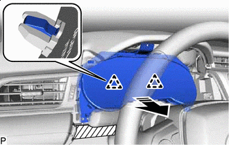
for Manual Tilt and Manual Telescopic Steering Column:
-
Release the tilt and telescopic lever and fully extend and lower the steering column assembly.
-
Lock the tilt and telescopic lever.
-
-
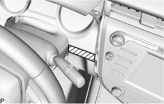

Protective Tape Apply protective tape to the area shown in the illustration.
-
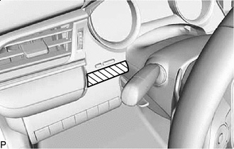
Protective Tape Apply protective tape to the area shown in the illustration.
-
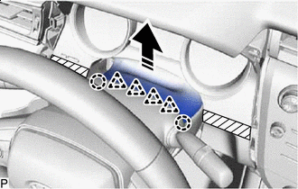

Remove in this Direction Disengage the 2 claws and 4 clips to separate the instrument cluster finish panel assembly.
-
Remove the 2 clips.
-
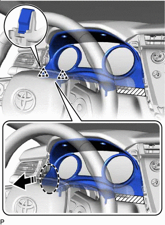

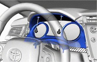
Place Hand Here Remove in this Direction Disengage the 2 clips as shown in the illustration.
-
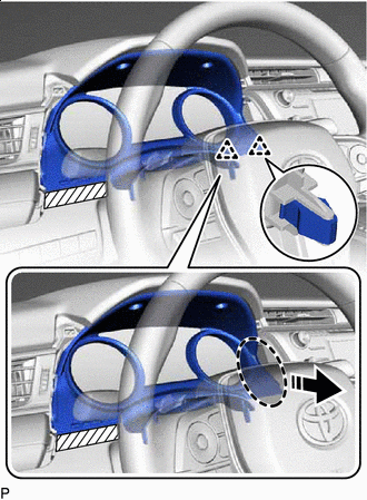
Place Hand Here Remove in this Direction Disengage the 2 clips as shown in the illustration.
-
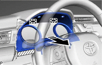
Remove in this Direction Disengage the 2 guides as shown in the illustration.
-
Disconnect the connector to remove the instrument cluster finish panel assembly.
-
-
REMOVE COMBINATION METER ASSEMBLY
-
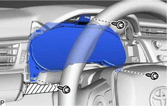
Remove the 3 screws.
-
Remove in this Direction Disengage the 2 clips as shown in the illustration.
-
Disengage the clamp.
-
Disconnect each connector to remove the combination meter assembly.
-