LIGHTING SYSTEM TERMINALS OF ECU
-
CHECK MAIN BODY ECU (MULTIPLEX NETWORK BODY ECU) AND INSTRUMENT PANEL JUNCTION BLOCK ASSEMBLY
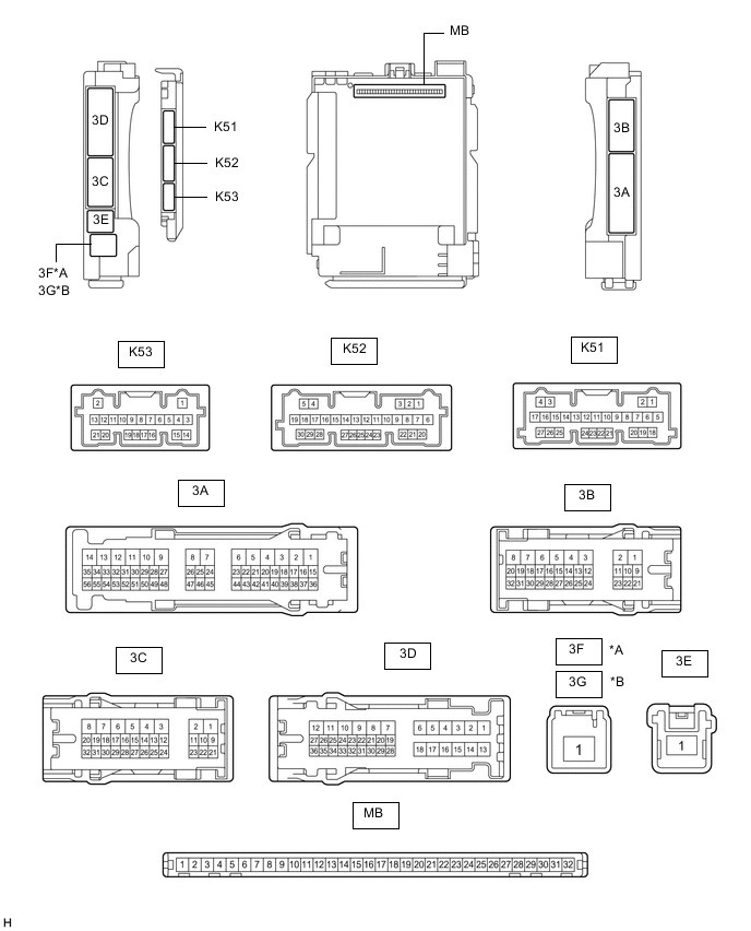
*A for LHD *B for RHD
-
Disconnect the instrument panel junction block assembly and main body ECU (multiplex network body ECU) connectors.
-
Measure the voltage and resistance according to the value(s) in the table below.
Terminal No. (Symbol) Wiring Color Terminal Description Condition Specified Condition 3B-3 - Body ground LA - Body ground Ground Always Below 1 Ω 3B-23 - Body ground*3 BE - Body ground Battery power supply Always 11 to 14 V 3C-1 - Body ground*4 LG - Body ground Battery power supply Always 11 to 14 V 3F-1 - Body ground*1 W - Body ground*5
B - Body ground*6
Battery power supply Always 11 to 14 V 3G-1 - Body ground*2 W - Body ground Battery power supply Always 11 to 14 V K51-19 (GND2) - Body ground W-B - Body ground Ground Always Below 1 Ω
-
*1: for LHD
-
*2: for RHD
-
*3: w/ Door Control Battery
-
*4: w/o Door Control Battery
-
*5: for Generator 100A Type
-
*6: for Generator 130A Type
-
-
Connect the instrument panel junction block assembly and main body ECU (multiplex network body ECU) connectors.
-
Measure the voltage and check for pulses according to the value(s) in the table below.
Terminal No. (Symbol) Wiring Color Terminal Description Condition Specified Condition 3A-17 - Body ground R - Body ground*1
LA-R - Body ground*2
IG power supply Ignition switch ON 11 to 14 V Ignition switch off Below 1 V 3A-30 - Body ground LG - Body ground ACC power supply Ignition switch ACC 11 to 14 V Ignition switch off Below 1 V 3A-31 - Body ground V - Body ground Rear door courtesy light switch assembly RH input Rear door RH open Below 1 V Rear door RH closed 11 to 14 V 3A-36 - Body ground*3 W - Body ground Footwell light LH (No. 1 interior illumination light assembly) drive output Footwell light LH (No. 1 interior illumination light assembly) off 11 to 14 V Footwell light LH (No. 1 interior illumination light assembly) dimmer control operating (dimming) Pulse generation Footwell light LH (No. 1 interior illumination light assembly) at full brightness Below 2.2 V 3A-37 - Body ground*3 B - Body ground Footwell light RH (No. 1 interior illumination light assembly) drive output Footwell light RH (No. 1 interior illumination light assembly) off 11 to 14 V Footwell light RH (No. 1 interior illumination light assembly) dimmer control operating (dimming) Pulse generation Footwell light RH (No. 1 interior illumination light assembly) at full brightness Below 2.2 V 3B-10 - Body ground B - Body ground Map light (roof console box sub-assembly), room light assembly*4, spot light assembly*5 and vanity light assembly power supply DOME CUT relay on 11 to 14 V DOME CUT relay off Below 1 V 3B-12 - Body ground GR - Body ground Front door unlock detection switch RH input Front door RH locked 11 to 14 V Front door RH unlocked Below 1 V 3B-13 - Body ground W - Body ground Front door unlock detection switch LH input Front door LH locked 11 to 14 V Front door LH unlocked Below 1 V 3B-14 - Body ground GR - Body ground Rear door unlock detection switch LH input Rear door LH locked 11 to 14 V Rear door LH unlocked Below 1 V 3B-24 - Body ground*2 LA-LG - Body ground Ignition key cylinder light (transponder key coil) power supply Always 11 to 14 V 3B-24 - Body ground*6 LG - Body ground Instrument panel ambient illumination light (instrument panel light assembly) power supply Always 11 to 14 V 3B-25 - Body ground*3 BE - Body ground Footwell light RH (No. 1 interior illumination light assembly) power supply Always 11 to 14 V 3B-26 - Body ground*7, *8 R - Body ground Front door inside handle illumination light (No. 1 interior illumination light assembly)*7 and rear door inside handle illumination light (No. 2 interior illumination light assembly)*8 power supply Always 11 to 14 V 3B-27 - Body ground*3 B - Body ground Footwell light LH (No. 1 interior illumination light assembly) power supply Always 11 to 14 V 3B-29 - Body ground G - Body ground*1
LA-G - Body ground*2
Illuminated entry system drive output Map light LH and map light RH (map light (roof console box sub-assembly))*5, room light assembly*4 and ignition key cylinder light (transponder key coil)*2 off (when operated by illuminated entry system) 11 to 14 V Map light LH and map light RH (map light (roof console box sub-assembly))*5, room light assembly*4 and ignition key cylinder light (transponder key coil)*2 on (when operated by illuminated entry system) Below 1 V 3D-19 - Body ground LA-B - Body ground No. 1 luggage compartment light assembly and courtesy light assembly power supply DOME CUT relay on 11 to 14 V DOME CUT relay off Below 1 V 3D-24 - Body ground G - Body ground Rear door courtesy light switch assembly LH input Rear door LH open Below 1 V Rear door LH closed 11 to 14 V 3D-34 - Body ground LA-GR - Body ground Luggage compartment door courtesy light switch (luggage compartment door lock assembly) input Luggage compartment door open Below 1 V Luggage compartment door closed 11 to 14 V K51-20 (LSWR) - Body ground L - Body ground Rear door unlock detection switch RH input Rear door RH locked 11 to 14 V Rear door RH unlocked Below 1 V K52-1 (FLCY) - Body ground W - Body ground Front door courtesy light switch assembly LH input Front door LH open Below 1 V Front door LH closed 11 to 14 V K52-2 (FLCL) - Body ground*9 G - Body ground Courtesy light assembly LH drive output Courtesy light assembly LH off 11 to 14 V Courtesy light assembly LH on Below 1 V K52-3 (FRCL) - Body ground*9 L - Body ground Courtesy light assembly RH drive output Courtesy light assembly RH off 11 to 14 V Courtesy light assembly RH on Below 1 V K52-6 (FRCY) - Body ground BE - Body ground Front door courtesy light switch assembly RH input Front door RH open Below 1 V Front door RH closed 11 to 14 V K52-20 (TCYL) - Body ground GR - Body ground No. 1 luggage compartment light assembly drive output No. 1 luggage compartment light assembly off 11 to 14 V No. 1 luggage compartment light assembly on Below 1 V K53-20 (LED1) - Body ground*6 W - Body ground Instrument panel ambient illumination light (instrument panel light assembly) drive output Instrument panel ambient illumination light (instrument panel light assembly) off 11 to 14 V Instrument panel ambient illumination light (instrument panel light assembly) dimmer control operating (dimming) Pulse generation Instrument panel ambient illumination light (instrument panel light assembly) at full brightness Below 2.2 V K53-21 (LED2) - Body ground*7, *8 R - Body ground Front door inside handle illumination light (No. 1 interior illumination light assembly)*7 and rear door inside handle illumination light (No. 2 interior illumination light assembly)*8 drive output Front door inside handle illumination light (No. 1 interior illumination light assembly)*7 and rear door inside handle illumination light (No. 2 interior illumination light assembly)*8 off 11 to 14 V Front door inside handle illumination light (No. 1 interior illumination light assembly)*7 and rear door inside handle illumination light (No. 2 interior illumination light assembly)*8 dimmer control operating (dimming) Pulse generation Front door inside handle illumination light (No. 1 interior illumination light assembly)*7 and rear door inside handle illumination light (No. 2 interior illumination light assembly)*8 at full brightness Below 2.2 V
-
*1: w/ Smart Entry and Start System
-
*2: w/o Smart Entry and Start System
-
*3: w/ Footwell Light
-
*4: w/ Room Light (for Bulb Type)
-
*5: w/ Room Light (for LED Type)
-
*6: w/ Instrument Panel Ambient Illumination Light
-
*7: w/ Front Door Inside Handle Illumination Light
-
*8: w/ Rear Door Inside Handle Illumination Light
-
*9: w/ Courtesy Light
-
-
-
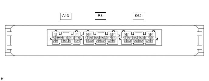
CHECK CERTIFICATION ECU (SMART KEY ECU ASSEMBLY) (w/ Smart Entry and Start System)
-
Measure the voltage according to the value(s) in the table below.
Terminal No. (Symbol) Wiring Color Terminal Description Condition Specified Condition K62-10 (SWIL) - K62-11 (AGND) W - BE Engine switch illumination drive output Engine switch illumination on 11 to 14 V Engine switch illumination off Below 1 V
-