IMMOBILISER SYSTEM(w/o Smart Entry and Start System), Diagnostic DTC:B2799
| DTC Code | DTC Name |
|---|---|
| B2799 | Engine Immobiliser System Malfunction |
DESCRIPTION
The ECM stores this DTC when a communication line between the ECM and transponder key ECU assembly is malfunctioning or the communication ID of the ECM and transponder key ECU assembly do not match.
| DTC No. | Detection Item | DTC Detection Condition | Trouble Area | Note |
|---|---|---|---|---|
| B2799 | Engine Immobiliser System Malfunction | One of the following conditions is met:
|
|
DTC Output Confirmation Operation: |
| Vehicle Condition when Malfunction Detected | Fail-safe Operation when Malfunction Detected |
|---|---|
| Engine cannot be started | - |
| DTC No. | Data List and Active Test |
|---|---|
| B2799 | - |
WIRING DIAGRAM
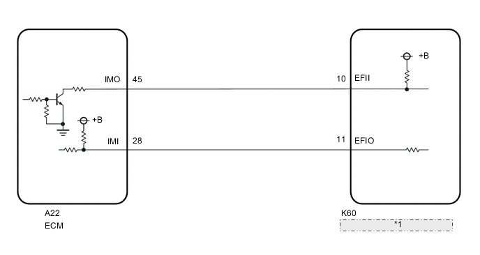
| *1 | Transponder Key ECU Assembly |
CAUTION / NOTICE / HINT
Note
-
If the transponder key ECU assembly or ECM is replaced, refer to Service Bulletin.
-
After repair, confirm that no DTCs are output by performing "DTC Output Confirmation Operation".
Tech Tips
If transponder key ECU assembly DTCs are output simultaneously, troubleshoot the transponder key ECU assembly DTCs first.
PROCEDURE
-
REGISTER ECU COMMUNICATION ID
-
Reregister the ECU communication ID.
Result Proceed to NEXT
NEXT 
-
-
INSPECT TRANSPONDER KEY ECU ASSEMBLY (TERMINAL EFII)
-
Using an oscilloscope, check the waveform.
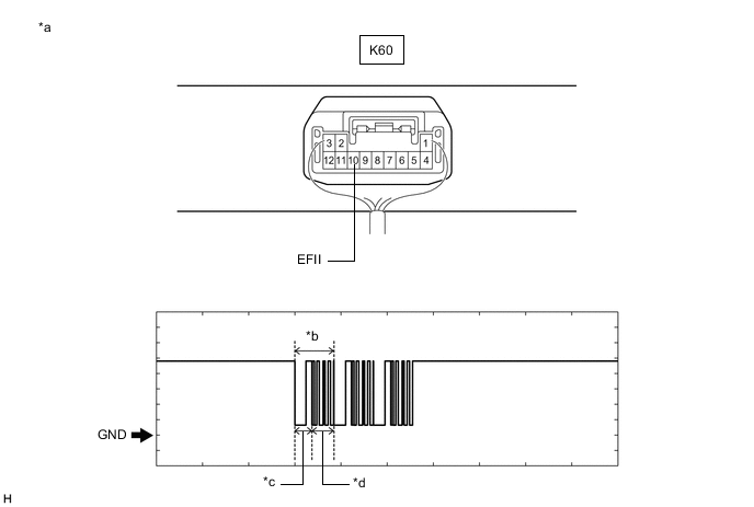
*a Component with harness connected
(Transponder Key ECU Assembly)
*b Waveform *c Approximately 160 ms. *d Approximately 270 ms. OK Tester Connection Condition Tool Setting Specified Condition K60-10 (EFII) - Body ground Within 3 seconds of starter operation and initial combustion, or within 3 seconds of ignition switch first being turned to ON after cable disconnected and reconnected to negative (-) battery terminal 2 V/DIV., 500 ms./DIV. Pulse generation
(See waveform)
OK Waveform is similar to that shown in the illustration. Result Result Proceed to OK A NG (Terminal EFII stuck low (2.4 V or less)) B NG (Terminal EFII stuck high (12 V) or abnormal waveform) C
B 
INSPECT ECM (IMO TERMINAL VOLTAGE) Click here
C 
REPLACE ECM Click here
A
-
-
INSPECT TRANSPONDER KEY ECU ASSEMBLY (TERMINAL EFIO)
-
Using an oscilloscope, check the waveform.
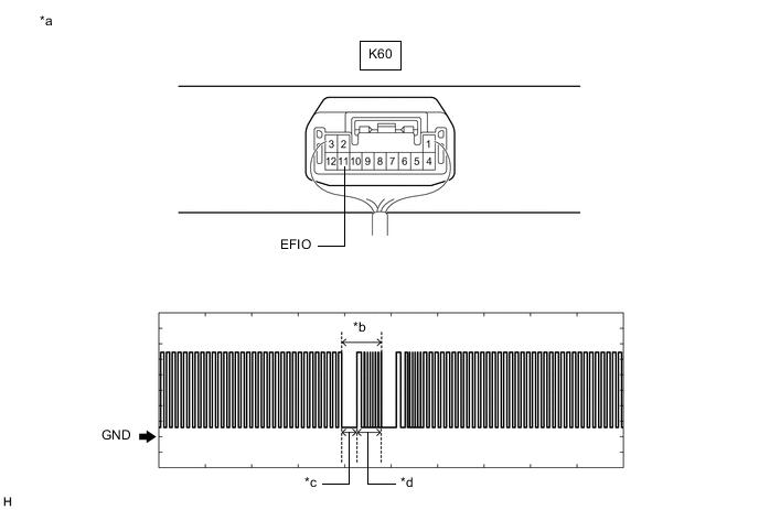
*a Component with harness connected
(Transponder Key ECU Assembly)
*b Waveform *c Approximately 160 ms. *d Approximately 270 ms. OK Tester Connection Condition Tool Setting Specified Condition K60-11 (EFIO) - Body ground Within 3 seconds of starter operation and initial combustion, or within 3 seconds of ignition switch first being turned to ON after cable disconnected and reconnected to negative (-) battery terminal 2 V/DIV., 500 ms./DIV. Pulse generation
(See waveform)
OK Waveform is similar to that shown in the illustration. Result Proceed to OK NG
NG
REPLACE TRANSPONDER KEY ECU ASSEMBLY
OK
-
-
REGISTER ECU COMMUNICATION ID
-
Reregister the ECU communication ID.
Result Proceed to NEXT
NEXT
-
-
CHECK WHETHER ENGINE STARTS
-
Using a registered door control transmitter assembly, turn the ignition switch to ON.
-
Check that the engine starts 5 seconds after the ignition switch was turned to ON.
OK Engine starts normally. Result Proceed to OK NG
OK
END (COMMUNICATION ID REGISTRATION WAS DEFECTIVE)
NG
REPLACE ECM Click here
-
-
INSPECT ECM (IMO TERMINAL VOLTAGE)
-
Disconnect the A22 ECM connector.
-
Turn the ignition switch to ON.
-
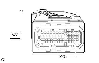
*a Front view of wire harness connector
(to ECM)
Measure the voltage according to the value(s) in the table below.
Standard Voltage Tester Connection Condition Result A22-45 (IMO) - Body ground Ignition switch turned to ON using registered door control transmitter assembly Terminal IMO stuck low (2.4 V or less) Terminal IMO stuck high (12 V) or abnormal waveform Result Result Proceed to Terminal IMO stuck low (2.4 V or less) A Terminal IMO stuck high (12 V) or abnormal waveform B
B
REPLACE ECM Click here
A
-
-
CHECK HARNESS AND CONNECTOR (TRANSPONDER KEY ECU ASSEMBLY - ECM)
-
Disconnect the K60 transponder key ECU assembly connector.
-
Measure the resistance according to the value(s) in the table below.
Standard Resistance Tester Connection Condition Specified Condition K60-10 (EFII) - A22-45 (IMO) Always Below 1 Ω K60-10 (EFII) or A22-45 (IMO) - Other terminals and body ground Always 10 kΩ or higher Result Proceed to OK NG
OK
REPLACE TRANSPONDER KEY ECU ASSEMBLY
NG
REPAIR OR REPLACE HARNESS OR CONNECTOR
-