IMMOBILISER SYSTEM(w/o Smart Entry and Start System), Diagnostic DTC:B2784
| DTC Code | DTC Name |
|---|---|
| B2784 | Antenna Coil Open / Short |
DESCRIPTION
When an open or short circuit is detected in the antenna coil built into the transponder key coil, the transponder key ECU assembly stores this DTC.
| DTC No. | Detection Item | DTC Detection Condition | Trouble Area | Note |
|---|---|---|---|---|
| B2784 | Antenna Coil Open / Short | The antenna coil in the transponder key coil is open/shorted. |
|
DTC Output Confirmation Operation: |
| Vehicle Condition when Malfunction Detected | Fail-safe Operation when Malfunction Detected |
|---|---|
| Engine cannot be started | - |
| DTC No. | Data List and Active Test |
|---|---|
| B2784 | Antenna Coil Status |
WIRING DIAGRAM
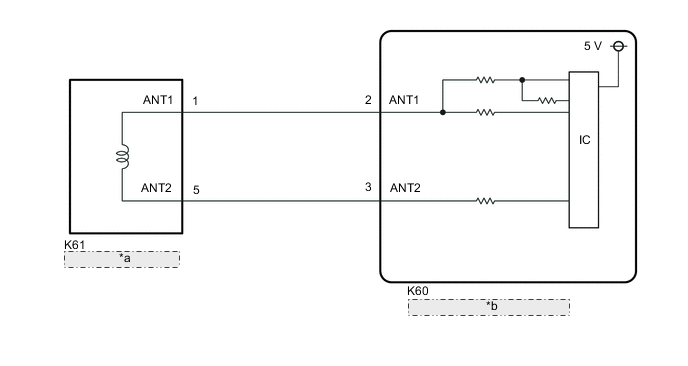
| *a | Transponder Key Coil |
| *b | Transponder Key ECU Assembly |
CAUTION / NOTICE / HINT
Note
-
If the transponder key ECU assembly is replaced, refer to Service Bulletin.
-
After repair, confirm that no DTCs are output by performing "DTC Output Confirmation Operation".
PROCEDURE
-
CHECK CONNECTION OF CONNECTOR
-
Check that the connector is properly connected to the transponder key coil.
Result Proceed to NEXT
NEXT 
-
-
CLEAR DTC
-
Clear the DTCs.
Body Electrical > Immobiliser > Clear DTCsResult Proceed to NEXT
NEXT
-
-
CHECK FOR DTC
-
Perform "DTC Output Confirmation Operation" procedure.
-
Check for DTCs.
Body Electrical > Immobiliser > Trouble CodesOK DTC B2784 is not output. Result Result Proceed to B2784 is not output A B2784 is output B
A 
END (CONNECTOR WAS NOT CONNECTED PROPERLY)
B
-
-
CHECK TRANSPONDER KEY COIL (OUTPUT)
-
Disconnect the K61 transponder key coil connector.
-
Using an oscilloscope, check the waveform.
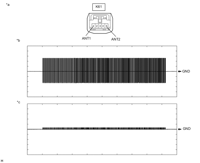
*a Front view of wire harness connector
(to Transponder Key Coil)
*b Waveform 1 *c Waveform 2 - - OK Tester Connection Condition Tool Setting Specified Condition K61-1 (ANT1) - Body ground Within 3 seconds of inserting door control transmitter assembly into ignition key cylinder 2 V/DIV., 500 ms./DIV. Pulse generation
(See waveform 1)
K61-5 (ANT2) - Body ground Within 3 seconds of inserting door control transmitter assembly into ignition key cylinder 2 V/DIV., 500 ms./DIV. Pulse generation
(See waveform 2)
OK Waveform is similar to that shown in the illustration. Result Proceed to OK NG
OK
REPLACE TRANSPONDER KEY COIL Click here
NG
-
-
CHECK HARNESS AND CONNECTOR (TRANSPONDER KEY ECU ASSEMBLY - TRANSPONDER KEY COIL)
-
Disconnect the K60 transponder key ECU assembly connector.
-
Measure the resistance according to the value(s) in the table below.
Standard Resistance Tester Connection Condition Specified Condition K60-2 (ANT1) - K61-1 (ANT1) Always Below 1 Ω K60-3 (ANT2) - K61-5 (ANT2) Always Below 1 Ω K60-2 (ANT1) or K61-1 (ANT1) - Other terminals and body ground Always 10 kΩ or higher K60-3 (ANT2) or K61-5 (ANT2) - Other terminals and body ground Always 10 kΩ or higher Result Proceed to OK NG
OK
REPLACE TRANSPONDER KEY ECU ASSEMBLY
NG
REPAIR OR REPLACE HARNESS OR CONNECTOR
-