CAUTION / NOTICE / HINT
The necessary procedures (adjustment, calibration, initialization, or registration) that must be performed after parts are removed and installed, or replaced during central gateway ECU (network gateway ECU) removal/installation are shown below.
| Replaced Part or Performed Procedure | Necessary Procedure | Effect/Inoperative Function when Necessary Procedure not Performed | Link |
|---|---|---|---|
| Battery terminal is disconnected/reconnected | Perform steering sensor zero point calibration | Lane departure alert system (w/ Steering Control) | |
| Pre-collision system | |||
| Memorize steering angle neutral point | Parking assist monitor system | ||
| Replacement of clearance warning ECU assembly*1 | Adjust TOYOTA parking assist-sensor system | TOYOTA parking assist-sensor system |
-
*1: w/ TOYOTA Parking Assist-sensor System
Some of these service operations affect the SRS airbag system. Read the precautionary notices concerning the SRS airbag system before servicing.
PROCEDURE
- Click here
PRECAUTION (for LHD)
Note:After turning the ignition switch off, waiting time may be required before disconnecting the cable from the negative (-) battery terminal. Therefore, make sure to read the disconnecting the cable from the negative (-) battery terminal notices before proceeding with work.
- Click here
DISCONNECT CABLE FROM NEGATIVE BATTERY TERMINAL (for LHD)
for 2AR-FE:
for A25A-FKS:
for 2GR-FKS:
CAUTION: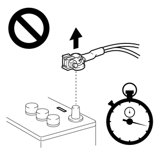
-
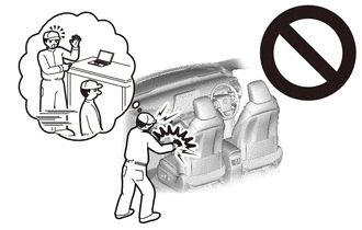
Wait at least 90 seconds after disconnecting the cable from the negative (-) battery terminal to disable the SRS system.
-
If an airbag deploys for any reason, it may cause a serious injury.
-
- Click here
REMOVE NO. 1 METER HOOD CLUSTER (for LHD)
- Click here
REMOVE NO. 2 INSTRUMENT PANEL GARNISH SUB-ASSEMBLY (for LHD)
- Click here
REMOVE INSTRUMENT PANEL FINISH PLATE GARNISH (for LHD)
- Click here
REMOVE FRONT DOOR SCUFF PLATE RH (for LHD)
- Click here
REMOVE COWL SIDE TRIM SUB-ASSEMBLY RH (for LHD)
- Click here
DISCONNECT FRONT DOOR OPENING TRIM WEATHERSTRIP RH (for LHD)
- Click here
REMOVE INSTRUMENT SIDE PANEL RH (for LHD)
- Click here
REMOVE NO. 2 INSTRUMENT PANEL UNDER COVER SUB-ASSEMBLY (for LHD)
- Click here
REMOVE LOWER NO. 2 INSTRUMENT PANEL AIRBAG ASSEMBLY (for LHD, w/ Passenger Side Knee Airbag)
- Click here
REMOVE LOWER INSTRUMENT PANEL SUB-ASSEMBLY (for LHD, w/o Passenger Side Knee Airbag)
- Click here
REMOVE LOWER INSTRUMENT PANEL SUB-ASSEMBLY (for LHD, w/ Passenger Side Knee Airbag)
- Click here
REMOVE ECU INTEGRATION BOX RH (for LHD, w/ ECU Integration Box RH)
-
Disconnect each connector.
-
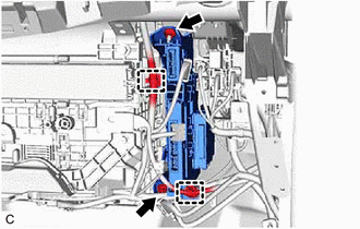
Disengage the 2 clamps.
-
Remove the bolt, nut and ECU integration box RH.
-
- Click here
REMOVE CENTRAL GATEWAY ECU (NETWORK GATEWAY ECU) (for LHD, w/o ECU Integration Box RH)
-
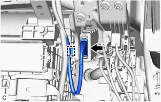
Disconnect the central gateway ECU (network gateway ECU) connector.
-
Disengage the clamp.
-
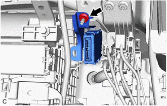
Remove the nut and central gateway ECU (network gateway ECU).
-
- Click here
REMOVE CENTRAL GATEWAY ECU (NETWORK GATEWAY ECU) (for LHD, w/ ECU Integration Box RH)
-
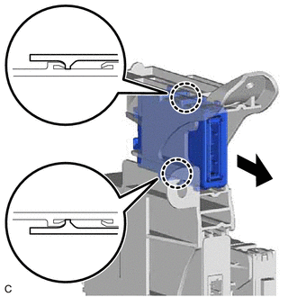
Disengage the 2 claws and remove the central gateway ECU (network gateway ECU).
Note:
-
If the ECU integration box is deformed or damaged, replace it.
-
Do not bend the 2 claws more than necessary.
-
-
- Click here
REMOVE LOWER NO. 1 INSTRUMENT PANEL AIRBAG ASSEMBLY (for RHD)
- Click here
REMOVE NO. 3 INSTRUMENT PANEL TO COWL BRACE SUB-ASSEMBLY (for RHD)
- Click here
REMOVE ECU INTEGRATION BOX RH (for RHD)
-
Disconnect each connector.
-
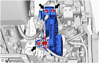
Disengage the clamp.
-
Remove the bolt, 2 nuts and ECU integration box RH.
-
- Click here
REMOVE CENTRAL GATEWAY ECU (NETWORK GATEWAY ECU) (for RHD)
-
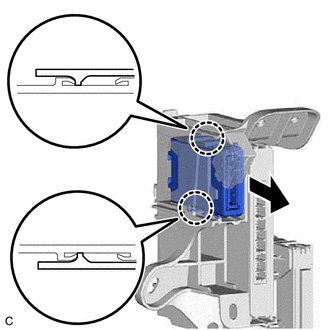
Disengage the 2 claws and remove the central gateway ECU (network gateway ECU).
Note:
-
If the ECU integration box is deformed or damaged, replace it.
-
Do not bend the 2 claws more than necessary.
-
-