CAN COMMUNICATION SYSTEM ECM Communication Stop Mode
DESCRIPTION
| Detection Item | Symptom | Trouble Area |
|---|---|---|
| ECM Communication Stop Mode | Any of the following conditions are met:
|
|
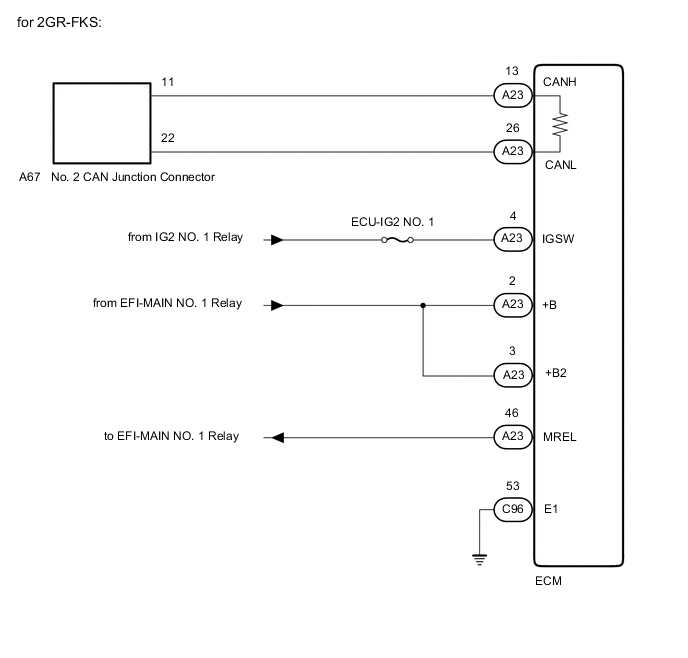
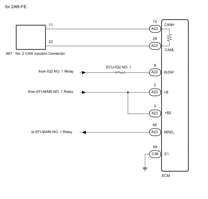
WIRING DIAGRAM

| *a | No. 2 CAN Junction Connector |
| *b | ECU-IG2 NO. 1 |
| *c | from IG2 NO. 1 Relay |
| *d | from EFI-MAIN NO. 1 Relay |
CAUTION / NOTICE / HINT
CAUTION:
When performing the confirmation driving pattern, obey all speed limits and traffic laws.
Note
-
Because the order of diagnosis is important to allow correct diagnosis, make sure to begin troubleshooting using How to Proceed with Troubleshooting when CAN communication system related DTCs are output.
-
Before measuring the resistance of the CAN bus, turn the ignition switch off and leave the vehicle for 1 minute or more without operating the key or any switches, or opening or closing the doors. After that, disconnect the cable from the negative (-) battery terminal and leave the vehicle for 1 minute or more before measuring the resistance.
-
After turning the ignition switch off, waiting time may be required before disconnecting the cable from the negative (-) battery terminal. Therefore, make sure to read the disconnecting the cable from the negative (-) battery terminal notices before proceeding with work.
-
After performing repairs, perform the DTC check procedure and confirm that the DTCs are not output again.
DTC check procedure: Turn the ignition switch to ON and wait for 1 minute or more. Then operate the suspected malfunctioning system and drive the vehicle at 60 km/h (37 mph) or more for 5 minutes or more.
-
After the repair, perform the CAN bus check and check that all the ECUs and sensors connected to the CAN communication system are displayed as normal.
-
Inspect the fuses for circuits related to this system before performing the following procedure.
Tech Tips
-
Before disconnecting related connectors for inspection, push in on each connector body to check that the connector is not loose or disconnected.
-
When a connector is disconnected, check that the terminals and connector body are not cracked, deformed or corroded.
PROCEDURE
-
CHECK VEHICLE TYPE
-
Check vehicle type.
Result Result Proceed to for A25A-FKS A for 2GR-FKS B for 2AR-FE C
B 
CHECK FOR OPEN IN CAN BUS LINES (ECM MAIN LINE) Click here
C
CHECK FOR OPEN IN CAN BUS LINES (ECM MAIN LINE) Click here
A 
-
-
CHECK FOR OPEN IN CAN BUS LINES (ECM MAIN LINE)
-
Disconnect the cable from the negative (-) battery terminal.
-
Disconnect the A24 ECM connector.
-
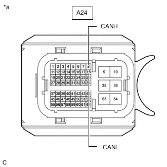
*a Front view of wire harness connector
(to ECM)
Measure the resistance according to the value(s) in the table below.
Standard Resistance Tester Connection Condition Specified Condition A24-8 (CANH) - A24-18 (CANL) Cable disconnected from negative (-) battery terminal 108 to 132 Ω Result Result OK NG
NG 
REPAIR OR REPLACE CAN MAIN BUS LINES OR CONNECTOR (ECM)
OK
-
-
CHECK ECM POWER SOURCE CIRCUIT
-
Check the ECM power source circuit.
Result Result OK NG
OK
REPLACE ECM Click here
NG
REPAIR OR REPLACE HARNESS OR CONNECTOR (POWER SOURCE CIRCUIT)
-
-
CHECK FOR OPEN IN CAN BUS LINES (ECM MAIN LINE)
-
Disconnect the cable from the negative (-) battery terminal.
-
Disconnect the A23 ECM connector.
-
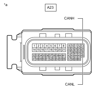
*a Front view of wire harness connector
(to ECM)
Measure the resistance according to the value(s) in the table below.
Standard Resistance Tester Connection Condition Specified Condition A23-13 (CANH) - A23-26 (CANL) Cable disconnected from negative (-) battery terminal 108 to 132 Ω Result Result OK NG
NG
REPAIR OR REPLACE CAN MAIN BUS LINES OR CONNECTOR (ECM)
OK
-
-
CHECK ECM POWER SOURCE CIRCUIT
-
Check the ECM power source circuit.
Result Result OK NG
OK
REPLACE ECM Click here
NG
REPAIR OR REPLACE HARNESS OR CONNECTOR (POWER SOURCE CIRCUIT)
-
-
CHECK FOR OPEN IN CAN BUS LINES (ECM MAIN LINE)
-
Disconnect the cable from the negative (-) battery terminal.
-
Disconnect the A22 ECM connector.
-
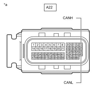
*a Front view of wire harness connector
(to ECM)
Measure the resistance according to the value(s) in the table below.
Standard Resistance Tester Connection Condition Specified Condition A22-13 (CANH) - A22-26 (CANL) Cable disconnected from negative (-) battery terminal 108 to 132 Ω Result Result OK NG
NG
REPAIR OR REPLACE CAN MAIN BUS LINES OR CONNECTOR (ECM)
OK
-
-
CHECK ECM POWER SOURCE CIRCUIT
-
Check the ECM power source circuit.
Result Result OK NG
OK
REPLACE ECM Click here
NG
REPAIR OR REPLACE HARNESS OR CONNECTOR (POWER SOURCE CIRCUIT)
-