CAN COMMUNICATION SYSTEM TERMINALS OF ECU
Note
-
After turning the ignition switch off, waiting time may be required before disconnecting the cable from the negative (-) battery terminal. Therefore, make sure to read the disconnecting the cable from the negative (-) battery terminal notices before proceeding with work.
-
Before measuring the resistance of the CAN bus, turn the ignition switch off and leave the vehicle for 1 minute or more without operating the key or any switches, or opening or closing the doors. After that, disconnect the cable from the negative (-) battery terminal and leave the vehicle for 1 minute or more before measuring the resistance.
-
This section describes the standard values for all CAN related components.
Tech Tips
-
The systems (ECUs and sensors) that use CAN communication vary depending on the vehicle and optional equipment. Check which systems (ECUs and sensors) are installed to the vehicle.
-
Operating the ignition switch, any other switches or a door triggers related ECU and sensor communication on the CAN. This communication will cause the resistance value to change.
-
Even after DTCs are cleared, if a DTC is stored again after driving the vehicle for a while, the malfunction may be occurring due to vibration of the vehicle. In such a case, wiggling the ECUs or wire harness while performing the inspection below may help determine the cause of the malfunction.
-
NO. 1 CAN JUNCTION CONNECTOR
-
Check the No. 1 CAN junction connector.
-
Connection diagram
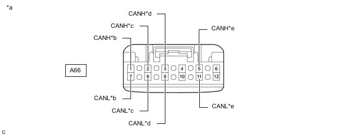
*a Front view of wire harness connector
(to No. 1 CAN Junction Connector)
*b to Millimeter Wave Radar Sensor Assembly
(w/ Toyota Safety Sense)
*c to Forward Recognition Camera
(w/ Toyota Safety Sense)
*d to Central Gateway ECU (Network Gateway ECU) *e to No. 5 CAN Junction Connector - - -
Check the connection diagram of the components which are connected to the No. 1 CAN junction connector.
Terminal No. (Symbol) Wiring Color Connected to A66-1 (CANH) R Millimeter wave radar sensor assembly*
(for Bus 1)
A66-7 (CANL) W A66-2 (CANH) G Forward recognition camera*
(for Bus 1)
A66-8 (CANL) W A66-3 (CANH) P Central gateway ECU (network gateway ECU)
(for Bus 1)
A66-9 (CANL) W A66-5 (CANH) B No. 5 CAN junction connector
(for Bus 1)
A66-11 (CANL) W
-
*: w/ Toyota Safety Sense
-
-
-
-
NO. 2 CAN JUNCTION CONNECTOR
-
Check the No. 2 CAN junction connector.
-
Connection diagram
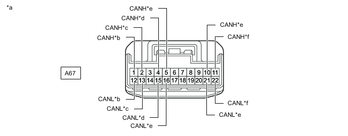
*a Front view of wire harness connector
(to No. 2 CAN Junction Connector)
*b to Brake Actuator Assembly *c to No. 3 Junction Connector *d to Rack and Pinion Power Steering Gear Assembly *e to No. 4 CAN Junction Connector *f to ECM -
Check the connection diagram of the components which are connected to the No. 2 CAN junction connector.
Terminal No. (Symbol) Wiring Color Connected to A67-1 (CANH) Y Brake actuator assembly
(for Bus 4)
A67-12 (CANL) W A67-2 (CANH) R No. 3 junction connector
(for Bus 4)
A67-13 (CANL) W A67-4 (CANH) G Rack and pinion power steering gear assembly
(for Bus 4)
A67-15 (CANL) W A67-5 (CANH) GR No. 4 CAN junction connector
(for Bus 4)
A67-16 (CANL) W A67-10 (CANH) L No. 4 CAN junction connector
(for Bus 2)
A67-21 (CANL) W A67-11 (CANH) B ECM
(for Bus 2)
A67-22 (CANL) W
-
-
-
NO. 3 CAN JUNCTION CONNECTOR
-
Check the No. 3 CAN junction connector.
-
Connection diagram
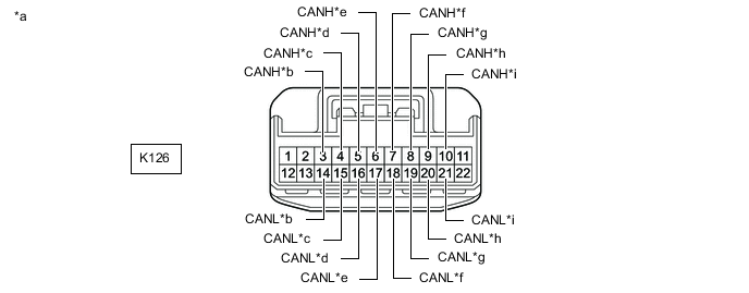
*a Front view of wire harness connector
(to No. 3 CAN Junction Connector)
*b to No. 1 Junction Connector *c to Certification ECU (Smart Key ECU Assembly)
(w/ Smart Entry and Start System)
*d to Combination Meter Assembly *e to Main Body ECU (Multiplex Network Body ECU) *f to Air Conditioning Amplifier Assembly *g to Headlight ECU Sub-assembly LH
(w/ Automatic Headlight Beam Level Control System)
*h to Meter Mirror Sub-assembly
(w/ Headup Display System)
*i to Multiplex Tilt and Telescopic ECU
(w/ Power Tilt and Power Telescopic System)
- - -
Check the connection diagram of the components which are connected to the No. 3 CAN junction connector.
Terminal No. (Symbol) Wiring Color Connected to K126-3 (CANH) P No. 1 junction connector
(for Bus 5)
K126-14 (CANL) W K126-4 (CANH) G Certification ECU (smart key ECU assembly)*1
(for Bus 5)
K126-15 (CANL) W K126-5 (CANH) B Combination meter assembly
(for Bus 5)
K126-16 (CANL) W K126-6 (CANH) BE Main body ECU (multiplex network body ECU)
(for Bus 5)
K126-17 (CANL) W K126-7 (CANH) SB Air conditioning amplifier assembly
(for Bus 5)
K126-18 (CANL) W K126-8 (CANH) L Headlight ECU sub-assembly LH*2
(for Bus 5)
K126-19 (CANL) W K126-9 (CANH) LG Meter mirror sub-assembly*3
(for Bus 5)
K126-20 (CANL) W K126-10 (CANH) R Multiplex tilt and telescopic ECU*4
(for Bus 5)
K126-21 (CANL) W
-
*1: w/ Smart Entry and Start System
-
*2: w/ Automatic Headlight Beam Level Control System
-
*3: w/ Headup Display System
-
*4: w/ Power Tilt and Power Telescopic System
-
-
-
-
NO. 4 CAN JUNCTION CONNECTOR
-
Check the No. 4 CAN junction connector.
-
Connection diagram
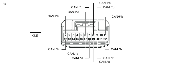
*a Front view of wire harness connector
(to No. 4 CAN Junction Connector)
*b to Central Gateway ECU (Network Gateway ECU) *c to No. 2 CAN Junction Connector *d to Steering Sensor *e to Accessory Gateway ECU (Network Gateway ECU)
(w/ Accessory Gateway ECU)
- - -
Check the connection diagram of the components which are connected to the No. 4 CAN junction connector.
Terminal No. (Symbol) Wiring Color Connected to K127-1 (CANH) SB Central gateway ECU (network gateway ECU)
(for Bus 2)
K127-12 (CANL) W K127-6 (CANH) SB No. 2 CAN junction connector
(for Bus 4)
K127-17 (CANL) W K127-7 (CANH) G Steering sensor
(for Bus 4)
K127-18 (CANL) W K127-8 (CANH) L Accessory gateway ECU (network gateway ECU)*
(for Bus 3)
K127-19 (CANL) W K127-9 (CANH) L Central gateway ECU (network gateway ECU)
(for Bus 3)
K127-20 (CANL) W K127-11 (CANH) GR Central gateway ECU (network gateway ECU)
(for Bus 3)
K127-22 (CANL) W
-
*: w/ Accessory Gateway ECU
-
-
-
Check the No. 4 CAN junction connector.
-
Connection diagram

*a Front view of wire harness connector
(to No. 4 CAN Junction Connector)
*b to Radio and Display Receiver Assembly
(w/ Radio and Display Type)
*c to Option Connector (Bus Buffer ECU)
(w/ CAN Compatible Optional Devices)
*d to Airbag Sensor Assembly *e to No. 2 CAN Junction Connector - - -
Check the connection diagram of the components which are connected to the No. 4 CAN junction connector.
Terminal No. (Symbol) Wiring Color Connected to K128-1 (CANH) B Radio and display receiver assembly*1
(for Bus 3)
K128-12 (CANL) W K128-3 (CANH) LG Option connector (bus buffer ECU)*2
(for Bus 3)
K128-14 (CANL) W K128-6 (CANH) R Airbag sensor assembly
(for Bus 4)
K128-17 (CANL) W K128-11 (CANH) G No. 2 CAN junction connector
(for Bus 2)
K128-22 (CANL) W
-
*1: w/ Radio and Display Type
-
*2: w/ CAN Compatible Optional Devices
-
-
-
-
NO. 5 CAN JUNCTION CONNECTOR
-
Check the No. 5 CAN junction connector.
-
Connection diagram
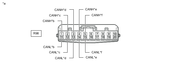
*a Front view of wire harness connector
(to No. 5 CAN Junction Connector)
*b to Central Gateway ECU (Network Gateway ECU) *c to Clearance Warning ECU Assembly
(w/ TOYOTA Parking Assist-sensor System)
*d to Blind Spot Monitor Sensor RH
(w/ Blind Spot Monitor System)
*e to Rear Television Camera Assembly
(w/ Parking Assist Monitor System)
*f to No. 1 CAN Junction Connector -
Check the connection diagram of the components which are connected to the No. 5 CAN junction connector.
Terminal No. (Symbol) Wiring Color Connected to R98-1 (CANH) GR Central gateway ECU (network gateway ECU)
(for Bus 1)
R98-11 (CANL) W R98-2 (CANH) L Clearance warning ECU assembly*1
(for Bus 1)
R98-12 (CANL) W R98-3 (CANH) BE Blind spot monitor sensor RH*2
(for Bus 1)
R98-13 (CANL) W R98-4 (CANH) R Rear television camera assembly*3
(for Bus 1)
R98-14 (CANL) W R98-5 (CANH) B No. 1 CAN junction connector
(for Bus 1)
R98-15 (CANL) W
-
*1: w/ TOYOTA Parking Assist-sensor System
-
*2: w/ Blind Spot Monitor System
-
*3: w/ Parking Assist Monitor System
-
-
-
-
NO. 6 CAN JUNCTION CONNECTOR (w/ Accessory Gateway ECU)
-
Check the No. 6 CAN junction connector.
Tech Tips
Connectors that connect to the No. 6 CAN junction connector can be distinguished by the color of their CAN bus lines. When the connectors have been disconnected from the No. 6 CAN junction connector, reconnecting the connectors to non-original positions on the No. 6 CAN junction connector does not affect system performance. However, it is preferred to reconnect the connectors to their original positions to avoid negative effects on the wiring such as tension on the wire harnesses, and to make future maintenance easier.
-
Connection diagram
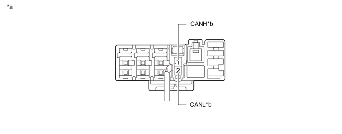
*a Component with harness connected
(No. 6 CAN Junction Connector)
*b to Accessory Gateway ECU (Network Gateway ECU) -
Check the connection diagram of the components which are connected to the No. 6 CAN junction connector.
Terminal No. (Symbol) Wiring Color Connected to K141-1 (CANH) R Accessory gateway ECU (network gateway ECU)
(for AG bus)
K141-2 (CANL) W
-
-
-
NO. 1 JUNCTION CONNECTOR
-
Check the No. 1 junction connector.
-
Connection diagram
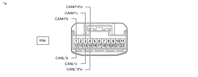
*a Front view of wire harness connector
(to No. 1 Junction Connector)
*b to Outer Mirror Control ECU Assembly (for Front Passenger Side)
(w/ Seat Position Memory System)
*c to No. 3 CAN Junction Connector *d to No. 5 Junction Connector
(for RHD)
*e to No. 6 Junction Connector
(for LHD)
- - -
Check the connection diagram of the components which are connected to the No. 1 junction connector.
Terminal No. (Symbol) Wiring Color Connected to R94-1 (CANH) LG Outer mirror control ECU assembly (for front passenger side)*1
(for Bus 5)
R94-12 (CANL) W R94-3 (CANH) B No. 3 CAN junction connector
(for Bus 5)
R94-14 (CANL) W R94-4 (CANH) L No. 5 junction connector*2
(for Bus 5)
R94-15 (CANL) W R94-4 (CANH) L No. 6 junction connector*3
(for Bus 5)
R94-15 (CANL) W
-
*1: w/ Seat Position Memory System
-
*2: for RHD
-
*3: for LHD
-
-
-
-
NO. 2 JUNCTION CONNECTOR
-
Check the No. 2 junction connector.
-
Connection diagram
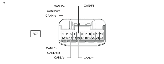
*a Front view of wire harness connector
(to No. 2 Junction Connector)
*b to Central Gateway ECU (Network Gateway ECU) *c to No. 5 Junction Connector
(for RHD)
*d to No. 6 Junction Connector
(for LHD)
*e to Outer Mirror Control ECU Assembly (for Driver Side)
(w/ Seat Position Memory System)
*f to Headlight ECU Sub-assembly RH
(w/ Automatic Headlight Beam Level Control System)
-
Check the connection diagram of the components which are connected to the No. 2 junction connector.
Terminal No. (Symbol) Wiring Color Connected to R97-1 (CANH) G Central gateway ECU (network gateway ECU)
(for Bus 5)
R97-12 (CANL) W R97-2 (CANH) L No. 5 junction connector*1
(for Bus 5)
R97-13 (CANL) W R97-2 (CANH) L No. 6 junction connector*2
(for Bus 5)
R97-13 (CANL) W R97-3 (CANH) GR Outer mirror control ECU assembly (for driver side)*3
(for Bus 5)
R97-14 (CANL) W R97-5 (CANH) G Headlight ECU sub-assembly RH*4
(for Bus 5)
R97-16 (CANL) W
-
*1: for RHD
-
*2: for LHD
-
*3: w/ Seat Position Memory System
-
*4: w/ Automatic Headlight Beam Level Control System
-
-
-
-
NO. 3 JUNCTION CONNECTOR
-
Check the No. 3 junction connector.
-
Connection diagram
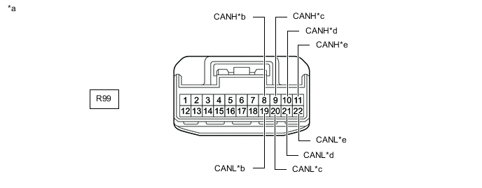
*a Front view of wire harness connector
(to No. 3 Junction Connector)
*b to Tire Pressure Warning ECU and Receiver
(w/ Tire Pressure Warning System and Tire Inflation Pressure Display Function)
*c to Occupant Detection ECU
(w/ Occupant Classification System)
*d to Central Gateway ECU (Network Gateway ECU) *e to No. 2 CAN Junction Connector - - -
Check the connection diagram of the components which are connected to the No. 3 junction connector.
Terminal No. (Symbol) Wiring Color Connected to R99-8 (CANH) L Tire pressure warning ECU and receiver*1
(for Bus 4)
R99-19 (CANL) W R99-9 (CANH) GR Occupant detection ECU*2
(for Bus 4)
R99-20 (CANL) W R99-10 (CANH) G Central gateway ECU (network gateway ECU)
(for Bus 4)
R99-21 (CANL) W R99-11 (CANH) LG No. 2 CAN junction connector
(for Bus 4)
R99-22 (CANL) W
-
*1: w/ Tire Pressure Warning System and Tire Inflation Pressure Display Function
-
*2: w/ Occupant Classification System
-
-
-
-
NO. 5 JUNCTION CONNECTOR (for RHD)
-
Check the No. 5 junction connector.
-
Connection diagram
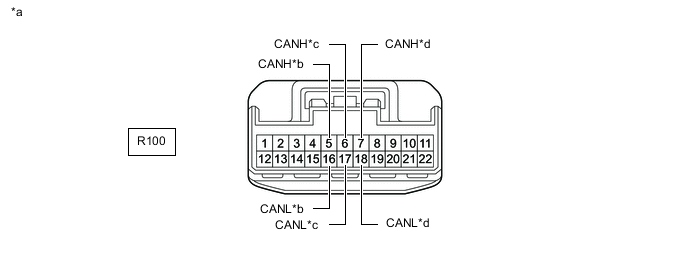
*a Front view of wire harness connector
(to No. 5 Junction Connector)
*b to No. 2 Junction Connector *c to No. 1 Junction Connector *d to Position Control ECU Assembly RH
(w/ Seat Position Memory System)
-
Check the connection diagram of the components which are connected to the No. 5 junction connector.
Terminal No. (Symbol) Wiring Color Connected to R100-5 (CANH) L No. 2 junction connector
(for Bus 5)
R100-16 (CANL) W R100-6 (CANH) L No. 1 junction connector
(for Bus 5)
R100-17 (CANL) W R100-7 (CANH) G Position control ECU assembly RH*
(for Bus 5)
R100-18 (CANL) W
-
*: w/ Seat Position Memory System
-
-
-
-
NO. 6 JUNCTION CONNECTOR (for LHD)
-
Check the No. 6 junction connector.
-
Connection diagram
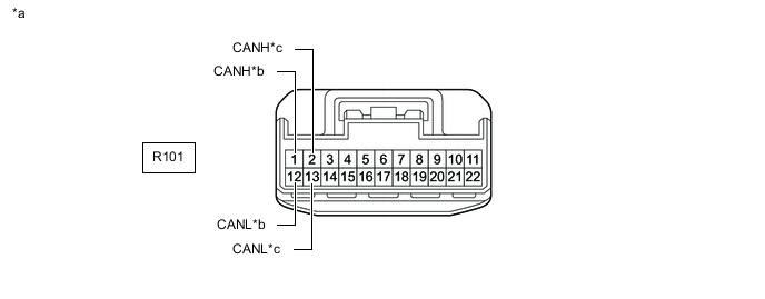
*a Front view of wire harness connector
(to No. 6 Junction Connector)
*b to No. 2 Junction Connector *c to No. 1 Junction Connector - - -
Check the connection diagram of the components which are connected to the No. 6 junction connector.
Terminal No. (Symbol) Wiring Color Connected to R101-1 (CANH) L No. 2 junction connector
(for Bus 5)
R101-12 (CANL) W R101-2 (CANH) L No. 1 junction connector
(for Bus 5)
R101-13 (CANL) W
-
-
-
DLC3
-
Disconnect the cable from the negative (-) battery terminal.
-
Measure the resistance according to the value(s) in the table below.
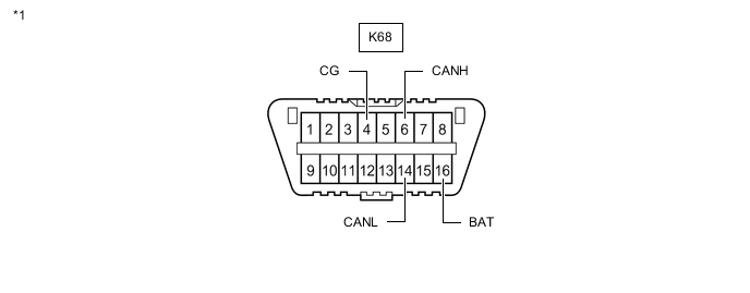
*1 DLC3 - -
-
-
CENTRAL GATEWAY ECU (NETWORK GATEWAY ECU)
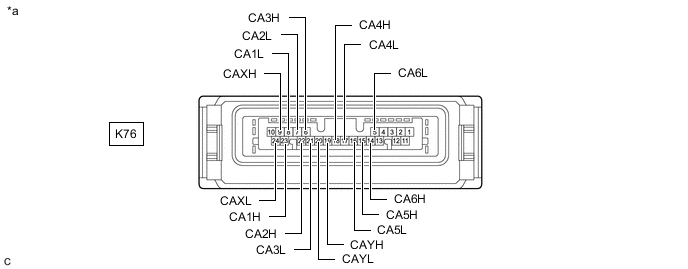
*a Component without harness connected
(Central Gateway ECU (Network Gateway ECU))
- -
-
Disconnect the cable from the negative (-) battery terminal.
-
Disconnect the K76 central gateway ECU (network gateway ECU) connector.
-
Measure the resistance according to the value(s) in the table below.
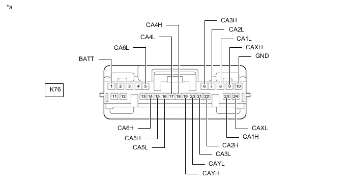
*a Front view of wire harness connector
(to Central Gateway ECU (Network Gateway ECU))
- -
-
-
ACCESSORY GATEWAY ECU (NETWORK GATEWAY ECU) (w/ Accessory Gateway ECU)
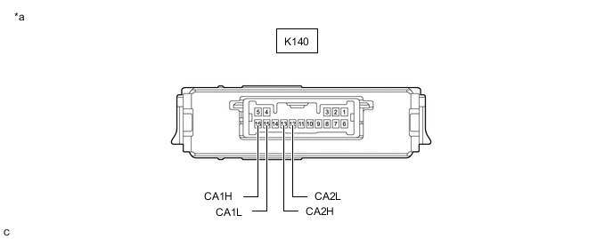
*a Component without harness connected
(Accessory Gateway ECU (Network Gateway ECU))
- -
-
Disconnect the cable from the negative (-) battery terminal.
-
Disconnect the K140 accessory gateway ECU (network gateway ECU) connector.
-
Measure the resistance according to the value(s) in the table below.
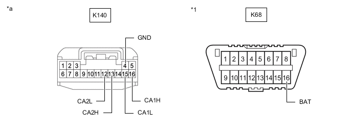
*1 DLC3 - - *a Front view of wire harness connector
(to Accessory Gateway ECU (Network Gateway ECU))
- -
-
-
STEERING SENSOR
-
Disconnect the cable from the negative (-) battery terminal.
-
Disconnect the K71 steering sensor connector.
-
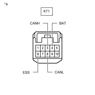
*a Front view of wire harness connector
(to Steering Sensor)
Measure the resistance according to the value(s) in the table below.
-
-
ECM (for A25A-FKS)
Refer to Terminals of ECU.
-
w/o Canister Pump Module
-
w/ Canister Pump Module
-
Disconnect the cable from the negative (-) battery terminal.
-
Disconnect the A24 ECM connector.
-
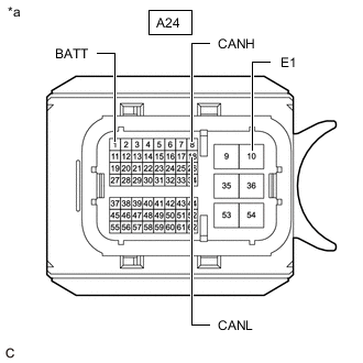
*a Front view of wire harness connector
(to ECM)
Measure the resistance according to the value(s) in the table below.
-
-
ECM (for 2GR-FKS)
Refer to Terminals of ECU.
-
Disconnect the cable from the negative (-) battery terminal.
-
Disconnect the A23 and C96 ECM connectors.
-
Measure the resistance according to the value(s) in the table below.
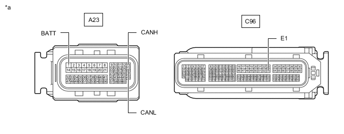
*a Front view of wire harness connector
(to ECM)
- -
-
-
ECM (for 2AR-FE)
Refer to Terminals of ECU.
-
Disconnect the cable from the negative (-) battery terminal.
-
Disconnect the A22 and C58 ECM connectors.
-
Measure the resistance according to the value(s) in the table below.
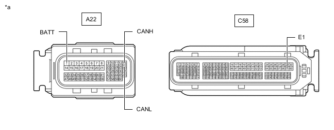
*a Front view of wire harness connector
(to ECM)
- -
-
-
BRAKE ACTUATOR ASSEMBLY
Refer to Terminals of ECU.
-
Disconnect the cable from the negative (-) battery terminal.
-
Disconnect the A34 brake actuator assembly connector.
-
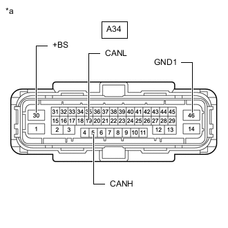
*a Front view of wire harness connector
(to Brake Actuator Assembly)
Measure the resistance according to the value(s) in the table below.
-
-
RACK AND PINION POWER STEERING GEAR ASSEMBLY
Refer to Terminals of ECU.
-
Disconnect the cable from the negative (-) battery terminal.
-
Disconnect the C71 rack and pinion power steering gear assembly connector.
-
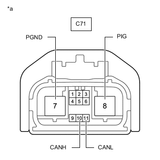
*a Front view of wire harness connector
(to Rack and Pinion Power Steering Gear Assembly)
Measure the resistance according to the value(s) in the table below.
-
-
COMBINATION METER ASSEMBLY
Refer to Terminals of ECU.
-
Disconnect the cable from the negative (-) battery terminal.
-
Disconnect the K21 combination meter assembly connector.
-
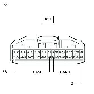
*a Front view of wire harness connector
(to Combination Meter Assembly)
Measure the resistance according to the value(s) in the table below.
-
-
METER MIRROR SUB-ASSEMBLY (w/ Headup Display System)
Refer to Terminals of ECU.
-
Disconnect the cable from the negative (-) battery terminal.
-
Disconnect the p1 meter mirror sub-assembly connector.
-
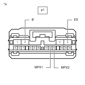
*a Front view of wire harness connector
(to Meter Mirror Sub-assembly)
Measure the resistance according to the value(s) in the table below.
-
-
MAIN BODY ECU (MULTIPLEX NETWORK BODY ECU)
Refer to Terminals of ECU.
-
Disconnect the cable from the negative (-) battery terminal.
-
Disconnect the K52 main body ECU (multiplex network body ECU) connector.
-
Measure the resistance according to the value(s) in the table below.
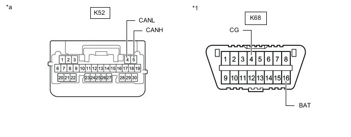
*1 DLC3 - - *a Front view of wire harness connector
(to Main Body ECU (Multiplex Network Body ECU))
- -
-
-
CERTIFICATION ECU (SMART KEY ECU ASSEMBLY) (w/ Smart Entry and Start System)
Refer to Terminals of ECU.
-
Disconnect the cable from the negative (-) battery terminal.
-
Disconnect the K62 certification ECU (smart key ECU assembly) connector.
-
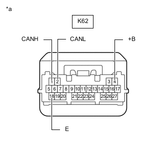
*a Front view of wire harness connector
(to Certification ECU (Smart Key ECU Assembly))
Measure the resistance according to the value(s) in the table below.
-
-
AIRBAG SENSOR ASSEMBLY
Refer to Terminals of ECU.
-
Disconnect the cable from the negative (-) battery terminal.
-
Disconnect the K73 airbag sensor assembly connector.
-
Measure the resistance according to the value(s) in the table below.
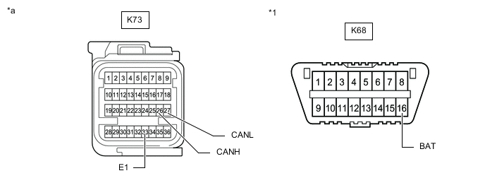
*1 DLC3 - - *a Front view of wire harness connector
(to Airbag Sensor Assembly)
- -
-
-
AIR CONDITIONING AMPLIFIER ASSEMBLY
Refer to Terminals of ECU.
-
for Automatic Air Conditioning System
-
for Manual Air Conditioning System
-
Disconnect the cable from the negative (-) battery terminal.
-
Disconnect the K54 air conditioning amplifier assembly connector.
-
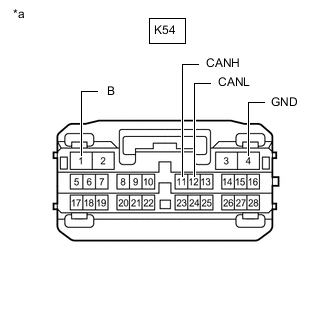
*a Front view of wire harness connector
(to Air Conditioning Amplifier Assembly)
Measure the resistance according to the value(s) in the table below.
-
-
RADIO AND DISPLAY RECEIVER ASSEMBLY (w/ Radio and Display Type)
Refer to Terminals of ECU.
-
for Audio and Visual System
-
for Navigation System
-
Disconnect the cable from the negative (-) battery terminal.
-
Disconnect the K2 radio and display receiver assembly connector.
-
Measure the resistance according to the value(s) in the table below.
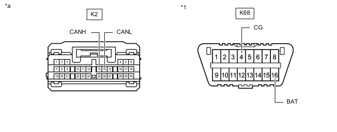
*1 DLC3 - - *a Front view of wire harness connector
(to Radio and Display Receiver Assembly)
- -
-
-
MULTIPLEX TILT AND TELESCOPIC ECU (w/ Power Tilt and Power Telescopic System)
Refer to Terminals of ECU.
-
Disconnect the cable from the negative (-) battery terminal.
-
Disconnect the K72 multiplex tilt and telescopic ECU connector.
-
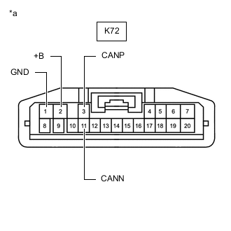
*a Front view of wire harness connector
(to Multiplex Tilt and Telescopic ECU)
Measure the resistance according to the value(s) in the table below.
-
*1: for LHD
-
*2: for RHD
-
-
-
POSITION CONTROL ECU ASSEMBLY RH (w/ Seat Position Memory System)
Refer to Terminals of ECU.
-
Disconnect the cable from the negative (-) battery terminal.
-
Disconnect the a10 and a12 position control ECU assembly RH connectors.
-
Measure the resistance according to the value(s) in the table below.
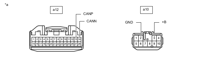
*a Front view of wire harness connector
(to Position Control ECU Assembly RH)
- -
-
-
OUTER MIRROR CONTROL ECU ASSEMBLY (FOR DRIVER SIDE) (w/ Seat Position Memory System)
Refer to Terminals of ECU.
-
Disconnect the cable from the negative (-) battery terminal.
-
Disconnect the N9 outer mirror control ECU assembly (for driver side) connector.
-
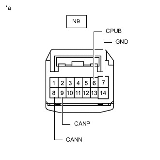
*a Front view of wire harness connector
(to Outer Mirror Control ECU Assembly (for Driver Side))
Measure the resistance according to the value(s) in the table below.
-
-
OUTER MIRROR CONTROL ECU ASSEMBLY (FOR FRONT PASSENGER SIDE) (w/ Seat Position Memory System)
Refer to Terminals of ECU.
-
Disconnect the cable from the negative (-) battery terminal.
-
Disconnect the O8 outer mirror control ECU assembly (for front passenger side) connector.
-

*a Front view of wire harness connector
(to Outer Mirror Control ECU Assembly (for Front Passenger Side))
Measure the resistance according to the value(s) in the table below.
-
-
HEADLIGHT ECU SUB-ASSEMBLY LH (w/ Automatic Headlight Beam Level Control System)
Refer to Terminals of ECU.
-
Disconnect the cable from the negative (-) battery terminal.
-
Disconnect the A10 headlight ECU sub-assembly LH connector.
-
Measure the resistance according to the value(s) in the table below.
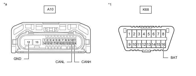
*1 DLC3 - - *a Front view of wire harness connector
(to Headlight ECU Sub-assembly LH)
- -
-
-
HEADLIGHT ECU SUB-ASSEMBLY RH (w/ Automatic Headlight Beam Level Control System)
Refer to Terminals of ECU.
-
Disconnect the cable from the negative (-) battery terminal.
-
Disconnect the A11 headlight ECU sub-assembly RH connector.
-
Measure the resistance according to the value(s) in the table below.

*1 DLC3 - - *a Front view of wire harness connector
(to Headlight ECU Sub-assembly RH)
- -
-
-
FORWARD RECOGNITION CAMERA (w/ Toyota Safety Sense)
Refer to Terminals of ECU.
-
Disconnect the cable from the negative (-) battery terminal.
-
Disconnect the V6 forward recognition camera connector.
-
Measure the resistance according to the value(s) in the table below.
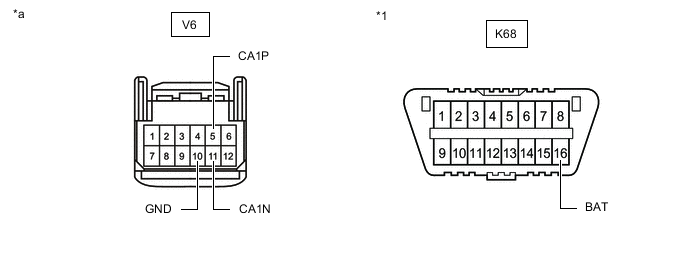
*1 DLC3 - - *a Front view of wire harness connector
(to Forward Recognition Camera)
- -
-
-
MILLIMETER WAVE RADAR SENSOR ASSEMBLY (w/ Toyota Safety Sense)
Refer to Terminals of ECU.
-
for 2AR-FE
-
except 2AR-FE
-
Disconnect the cable from the negative (-) battery terminal.
-
Disconnect the A30 millimeter wave radar sensor assembly connector.
-
Measure the resistance according to the value(s) in the table below.
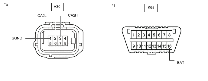
*1 DLC3 - - *a Front view of wire harness connector
(to Millimeter Wave Radar Sensor Assembly)
- -
-
-
CLEARANCE WARNING ECU ASSEMBLY (w/ TOYOTA Parking Assist-sensor System)
Refer to Terminals of ECU.
-
Disconnect the cable from the negative (-) battery terminal.
-
Disconnect the R39 clearance warning ECU assembly connector.
-
Measure the resistance according to the value(s) in the table below.
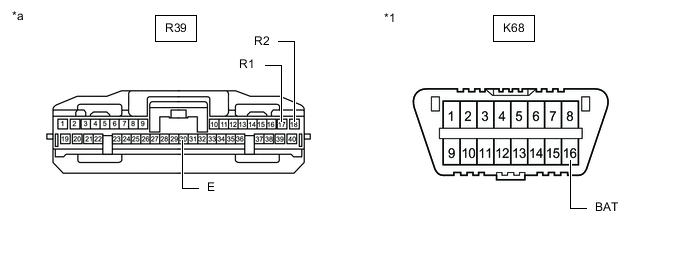
*1 DLC3 - - *a Front view of wire harness connector
(to Clearance Warning ECU Assembly)
- -
-
-
BLIND SPOT MONITOR SENSOR RH (w/ Blind Spot Monitor System)
Refer to Terminals of ECU.
-
Disconnect the cable from the negative (-) battery terminal.
-
Disconnect the W5 blind spot monitor sensor RH connector.
-
Measure the resistance according to the value(s) in the table below.
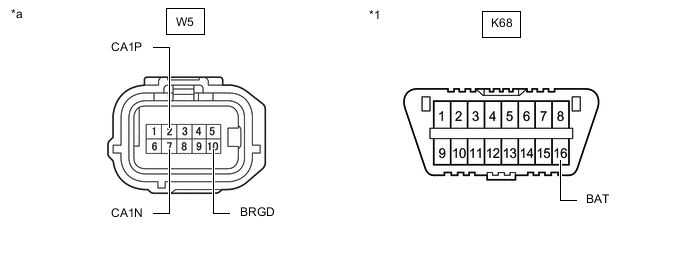
*1 DLC3 - - *a Front view of wire harness connector
(to Blind Spot Monitor Sensor RH)
- -
-
-
REAR TELEVISION CAMERA ASSEMBLY (w/ Parking Assist Monitor System)
Refer to Terminals of ECU.
-
Disconnect the cable from the negative (-) battery terminal.
-
Disconnect the m3 rear television camera assembly connector.
-
Measure the resistance according to the value(s) in the table below.
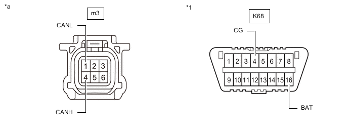
*1 DLC3 - - *a Front view of wire harness connector
(to Rear Television Camera Assembly)
- -
-
-
TIRE PRESSURE WARNING ECU AND RECEIVER (w/ Tire Pressure Warning System and Tire Inflation Pressure Display Function)
Refer to Terminals of ECU.
-
Disconnect the cable from the negative (-) battery terminal.
-
Disconnect the R9 tire pressure warning ECU and receiver connector.
-
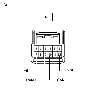
*a Front view of wire harness connector
(to Tire Pressure Warning ECU and Receiver)
Measure the resistance according to the value(s) in the table below.
-
-
OCCUPANT DETECTION ECU (w/ Occupant Classification System)
Refer to Terminals of ECU.
-
Disconnect the cable from the negative (-) battery terminal.
-
Disconnect the a20 occupant detection ECU connector.
-
Measure the resistance according to the value(s) in the table below.
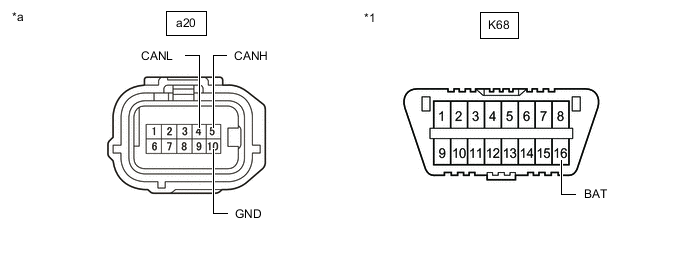
*1 DLC3 - - *a Front view of wire harness connector
(to Occupant Detection ECU)
- -
-
-
OPTION CONNECTOR (BUS BUFFER ECU) (w/ CAN Compatible Optional Devices)
-
Disconnect the cable from the negative (-) battery terminal.
-
Disconnect the K143 option connector (bus buffer ECU).
Tech Tips
Disconnect any CAN compatible optional devices from the option connector.
-
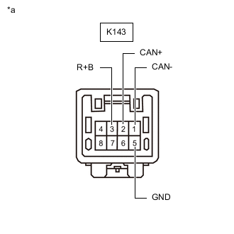
*a Front view of wire harness connector
(to Option Connector (Bus Buffer ECU))
Measure the resistance according to the value(s) in the table below.
-