CAN COMMUNICATION SYSTEM TERMINALS OF ECU
Note
-
After turning the ignition switch off, waiting time may be required before disconnecting the cable from the negative (-) battery terminal. Therefore, make sure to read the disconnecting the cable from the negative (-) battery terminal notices before proceeding with work.
-
Before measuring the resistance of the CAN bus, turn the ignition switch off and leave the vehicle for 1 minute or more without operating the key or any switches, or opening or closing the doors. After that, disconnect the cable from the negative (-) battery terminal and leave the vehicle for 1 minute or more before measuring the resistance.
-
This section describes the standard values for all CAN related components.
Tech Tips
-
The systems (ECUs and sensors) that use CAN communication vary depending on the vehicle and optional equipment. Check which systems (ECUs and sensors) are installed to the vehicle.
-
Operating the ignition switch, any other switches or a door triggers related ECU and sensor communication on the CAN. This communication will cause the resistance value to change.
-
Even after DTCs are cleared, if a DTC is stored again after driving the vehicle for a while, the malfunction may be occurring due to vibration of the vehicle. In such a case, wiggling the ECUs or wire harness while performing the inspection below may help determine the cause of the malfunction.
-
NO. 1 CAN JUNCTION CONNECTOR
-
Check the No. 1 CAN junction connector.
-
Connection diagram
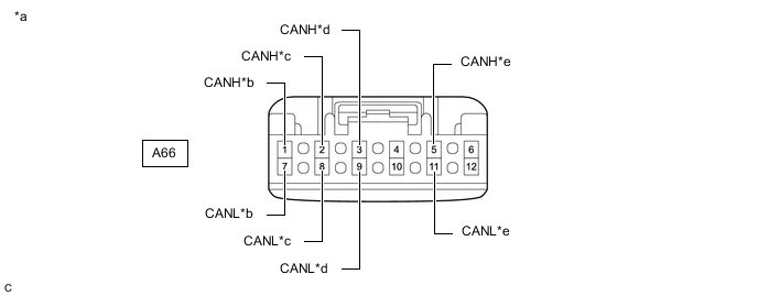
*a Front view of wire harness connector
(to No. 1 CAN Junction Connector)
*b to Millimeter Wave Radar Sensor Assembly
(w/ Toyota Safety Sense)
*c to Forward Recognition Camera
(w/ Toyota Safety Sense)
*d to Central Gateway ECU (Network Gateway ECU) *e to No. 5 CAN Junction Connector - - -
Check the connection diagram of the components which are connected to the No. 1 CAN junction connector.
Terminal No. (Symbol) Wiring Color Connected to A66-1 (CANH) R Millimeter wave radar sensor assembly*
(for Bus 1)
A66-7 (CANL) W A66-2 (CANH) G Forward recognition camera*
(for Bus 1)
A66-8 (CANL) W A66-3 (CANH) P Central gateway ECU (network gateway ECU)
(for Bus 1)
A66-9 (CANL) W A66-5 (CANH) B No. 5 CAN junction connector
(for Bus 1)
A66-11 (CANL) W
-
*: w/ Toyota Safety Sense
-
-
-
-
NO. 2 CAN JUNCTION CONNECTOR
-
Check the No. 2 CAN junction connector.
-
Connection diagram
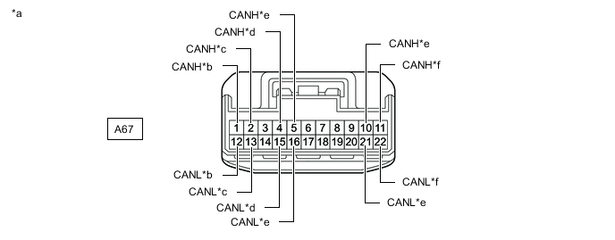
*a Front view of wire harness connector
(to No. 2 CAN Junction Connector)
*b to Brake Actuator Assembly *c to No. 3 Junction Connector *d to Rack and Pinion Power Steering Gear Assembly *e to No. 4 CAN Junction Connector *f to ECM -
Check the connection diagram of the components which are connected to the No. 2 CAN junction connector.
Terminal No. (Symbol) Wiring Color Connected to A67-1 (CANH) Y Brake actuator assembly
(for Bus 4)
A67-12 (CANL) W A67-2 (CANH) R No. 3 junction connector
(for Bus 4)
A67-13 (CANL) W A67-4 (CANH) G Rack and pinion power steering gear assembly
(for Bus 4)
A67-15 (CANL) W A67-5 (CANH) GR No. 4 CAN junction connector
(for Bus 4)
A67-16 (CANL) W A67-10 (CANH) L No. 4 CAN junction connector
(for Bus 2)
A67-21 (CANL) W A67-11 (CANH) B ECM
(for Bus 2)
A67-22 (CANL) W
-
-
-
NO. 3 CAN JUNCTION CONNECTOR
-
Check the No. 3 CAN junction connector.
-
Connection diagram
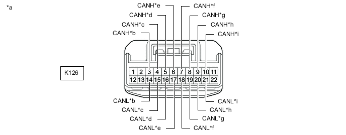
*a Front view of wire harness connector
(to No. 3 CAN Junction Connector)
*b to No. 1 Junction Connector *c to Certification ECU (Smart Key ECU Assembly)
(w/ Smart Entry and Start System)
*d to Combination Meter Assembly *e to Main Body ECU (Multiplex Network Body ECU) *f to Air Conditioning Amplifier Assembly *g to Headlight ECU Sub-assembly LH *h to Meter Mirror Sub-assembly
(w/ Headup Display System)
*i to Multiplex Tilt and Telescopic ECU
(w/ Power Tilt and Power Telescopic System)
- - -
Check the connection diagram of the components which are connected to the No. 3 CAN junction connector.
Terminal No. (Symbol) Wiring Color Connected to K126-3 (CANH) P No. 1 junction connector
(for Bus 5)
K126-14 (CANL) W K126-4 (CANH) G Certification ECU (smart key ECU assembly)*1
(for Bus 5)
K126-15 (CANL) W K126-5 (CANH) B Combination meter assembly
(for Bus 5)
K126-16 (CANL) W K126-6 (CANH) BE Main body ECU (multiplex network body ECU)
(for Bus 5)
K126-17 (CANL) W K126-7 (CANH) SB Air conditioning amplifier assembly
(for Bus 5)
K126-18 (CANL) W K126-8 (CANH) L Headlight ECU sub-assembly LH
(for Bus 5)
K126-19 (CANL) W K126-9 (CANH) LG Meter mirror sub-assembly*2
(for Bus 5)
K126-20 (CANL) W K126-10 (CANH) R Multiplex tilt and telescopic ECU*3
(for Bus 5)
K126-21 (CANL) W
-
*1: w/ Smart Entry and Start System
-
*2: w/ Headup Display System
-
*3: w/ Power Tilt and Power Telescopic System
-
-
-
-
NO. 4 CAN JUNCTION CONNECTOR
-
Check the No. 4 CAN junction connector.
-
Connection diagram
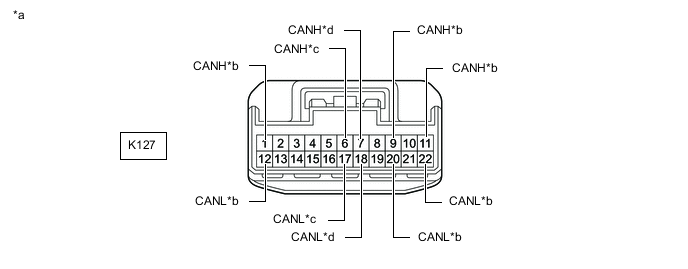
*a Front view of wire harness connector
(to No. 4 CAN Junction Connector)
*b to Central Gateway ECU (Network Gateway ECU) *c to No. 2 CAN Junction Connector *d to Steering Sensor -
Check the connection diagram of the components which are connected to the No. 4 CAN junction connector.
Terminal No. (Symbol) Wiring Color Connected to K127-1 (CANH) SB Central gateway ECU (network gateway ECU)
(for Bus 2)
K127-12 (CANL) W K127-6 (CANH) SB No. 2 CAN junction connector
(for Bus 4)
K127-17 (CANL) W K127-7 (CANH) G Steering sensor
(for Bus 4)
K127-18 (CANL) W K127-9 (CANH) L Central gateway ECU (network gateway ECU)
(for Bus 3)
K127-20 (CANL) W K127-11 (CANH) GR Central gateway ECU (network gateway ECU)
(for Bus 3)
K127-22 (CANL) W
-
-
Check the No. 4 CAN junction connector.
-
Connection diagram
*a Front view of wire harness connector
(to No. 4 CAN Junction Connector)
*b to Radio and Display Receiver Assembly
(w/ Radio and Display Type)
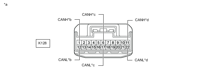
*c to Airbag Sensor Assembly *d to No. 2 CAN Junction Connector -
Check the connection diagram of the components which are connected to the No. 4 CAN junction connector.
Terminal No. (Symbol) Wiring Color Connected to K128-1 (CANH) B Radio and display receiver assembly*
(for Bus 3)
K128-12 (CANL) W K128-6 (CANH) R Airbag sensor assembly
(for Bus 4)
K128-17 (CANL) W K128-11 (CANH) G No. 2 CAN junction connector
(for Bus 2)
K128-22 (CANL) W
-
*: w/ Radio and Display Type
-
-
-
-
NO. 5 CAN JUNCTION CONNECTOR
-
Check the No. 5 CAN junction connector.
-
Connection diagram
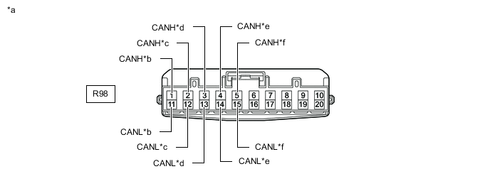
*a Front view of wire harness connector
(to No. 5 CAN Junction Connector)
*b to Central Gateway ECU (Network Gateway ECU) *c to Clearance Warning ECU Assembly
(w/ TOYOTA Parking Assist-sensor System)
*d to Blind Spot Monitor Sensor RH
(w/ Blind Spot Monitor System)
*e to Rear Television Camera Assembly
(w/ Parking Assist Monitor System)
*f to No. 1 CAN Junction Connector -
Check the connection diagram of the components which are connected to the No. 5 CAN junction connector.
Terminal No. (Symbol) Wiring Color Connected to R98-1 (CANH) GR Central gateway ECU (network gateway ECU)
(for Bus 1)
R98-11 (CANL) W R98-2 (CANH) L Clearance warning ECU assembly*1
(for Bus 1)
R98-12 (CANL) W R98-3 (CANH) BE Blind spot monitor sensor RH*2
(for Bus 1)
R98-13 (CANL) W R98-4 (CANH) R Rear television camera assembly*3
(for Bus 1)
R98-14 (CANL) W R98-5 (CANH) B No. 1 CAN junction connector
(for Bus 1)
R98-15 (CANL) W
-
*1: w/ TOYOTA Parking Assist-sensor System
-
*2: w/ Blind Spot Monitor System
-
*3: w/ Parking Assist Monitor System
-
-
-
-
NO. 1 JUNCTION CONNECTOR
-
Check the No. 1 junction connector.
-
Connection diagram
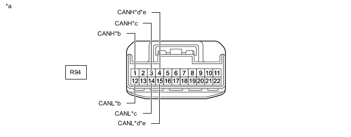
*a Front view of wire harness connector
(to No. 1 Junction Connector)
*b to Outer Mirror Control ECU Assembly (for Front Passenger Side)
(w/ Seat Position Memory System)
*c to No. 3 CAN Junction Connector *d to No. 5 Junction Connector
(for RHD)
*e to No. 6 Junction Connector
(for LHD)
- - -
Check the connection diagram of the components which are connected to the No. 1 junction connector.
Terminal No. (Symbol) Wiring Color Connected to R94-1 (CANH) LG Outer mirror control ECU assembly (for front passenger side)*1
(for Bus 5)
R94-12 (CANL) W R94-3 (CANH) B No. 3 CAN junction connector
(for Bus 5)
R94-14 (CANL) W R94-4 (CANH) L No. 5 junction connector*2
(for Bus 5)
R94-15 (CANL) W R94-4 (CANH) L No. 6 junction connector*3
(for Bus 5)
R94-15 (CANL) W
-
*1: w/ Seat Position Memory System
-
*2: for RHD
-
*3: for LHD
-
-
-
-
NO. 2 JUNCTION CONNECTOR
-
Check the No. 2 junction connector.
-
Connection diagram
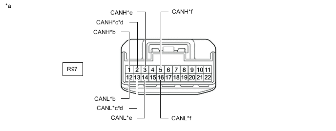
*a Front view of wire harness connector
(to No. 2 Junction Connector)
*b to Central Gateway ECU (Network Gateway ECU) *c to No. 5 Junction Connector
(for RHD)
*d to No. 6 Junction Connector
(for LHD)
*e to Outer Mirror Control ECU Assembly (for Driver Side)
(w/ Seat Position Memory System)
*f to Headlight ECU Sub-assembly RH -
Check the connection diagram of the components which are connected to the No. 2 junction connector.
Terminal No. (Symbol) Wiring Color Connected to R97-1 (CANH) G Central gateway ECU (network gateway ECU)
(for Bus 5)
R97-12 (CANL) W R97-2 (CANH) L No. 5 junction connector*1
(for Bus 5)
R97-13 (CANL) W R97-2 (CANH) L No. 6 junction connector*2
(for Bus 5)
R97-13 (CANL) W R97-3 (CANH) GR Outer mirror control ECU assembly (for driver side)*3
(for Bus 5)
R97-14 (CANL) W R97-5 (CANH) G Headlight ECU sub-assembly RH
(for Bus 5)
R97-16 (CANL) W
-
*1: for RHD
-
*2: for LHD
-
*3: w/ Seat Position Memory System
-
-
-
-
NO. 3 JUNCTION CONNECTOR
-
Check the No. 3 junction connector.
-
Connection diagram
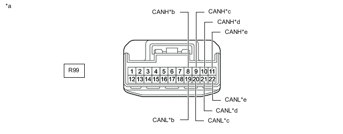
*a Front view of wire harness connector
(to No. 3 Junction Connector)
*b to Tire Pressure Warning ECU and Receiver
(w/ Tire Pressure Warning System)
*c to Occupant Detection ECU
(w/ Occupant Classification System)
*d to Central Gateway ECU (Network Gateway ECU) *e to No. 2 CAN Junction Connector - - -
Check the connection diagram of the components which are connected to the No. 3 junction connector.
Terminal No. (Symbol) Wiring Color Connected to R99-8 (CANH) L Tire pressure warning ECU and receiver*1
(for Bus 4)
R99-19 (CANL) W R99-9 (CANH) GR Occupant detection ECU*2
(for Bus 4)
R99-20 (CANL) W R99-10 (CANH) G Central gateway ECU (network gateway ECU)
(for Bus 4)
R99-21 (CANL) W R99-11 (CANH) LG No. 2 CAN junction connector
(for Bus 4)
R99-22 (CANL) W
-
*1: w/ Tire Pressure Warning System
-
*2: w/ Occupant Classification System
-
-
-
-
NO. 5 JUNCTION CONNECTOR (for RHD)
-
Check the No. 5 junction connector.
-
Connection diagram
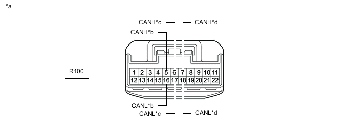
*a Front view of wire harness connector
(to No. 5 Junction Connector)
*b to No. 2 Junction Connector *c to No. 1 Junction Connector *d to Position Control ECU Assembly RH
(w/ Seat Position Memory System)
-
Check the connection diagram of the components which are connected to the No. 5 junction connector.
Terminal No. (Symbol) Wiring Color Connected to R100-5 (CANH) L No. 2 junction connector
(for Bus 5)
R100-16 (CANL) W R100-6 (CANH) L No. 1 junction connector
(for Bus 5)
R100-17 (CANL) W R100-7 (CANH) G Position control ECU assembly RH*
(for Bus 5)
R100-18 (CANL) W
-
*: w/ Seat Position Memory System
-
-
-
-
NO. 6 JUNCTION CONNECTOR (for LHD)
-
Check the No. 6 junction connector.
-
Connection diagram
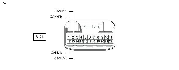
*a Front view of wire harness connector
(to No. 6 Junction Connector)
*b to No. 2 Junction Connector *c to No. 1 Junction Connector - - -
Check the connection diagram of the components which are connected to the No. 6 junction connector.
Terminal No. (Symbol) Wiring Color Connected to R101-1 (CANH) L No. 2 junction connector
(for Bus 5)
R101-12 (CANL) W R101-2 (CANH) L No. 1 junction connector
(for Bus 5)
R101-13 (CANL) W
-
-
-
DLC3
-
Disconnect the cable from the negative (-) battery terminal.
-
Measure the resistance according to the value(s) in the table below.
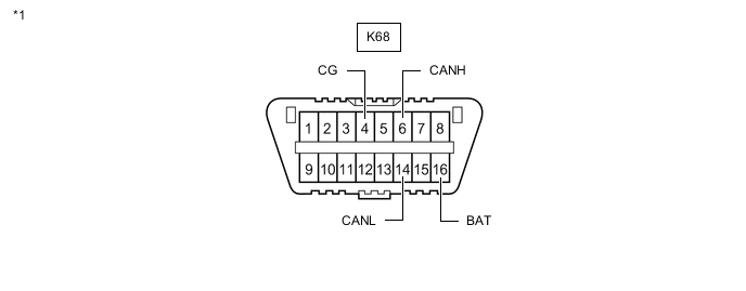
*1 DLC3 - -
-
-
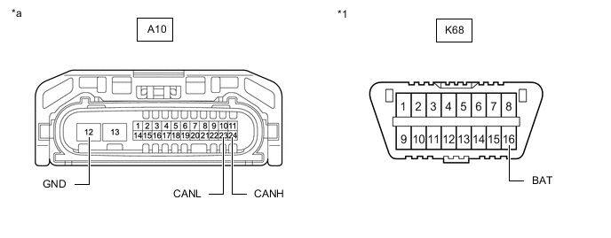
CENTRAL GATEWAY ECU (NETWORK GATEWAY ECU)
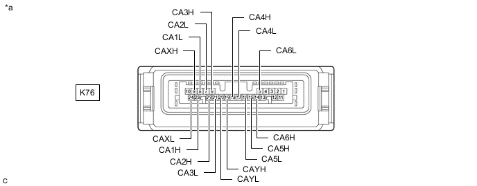
*a Component without harness connected
(Central Gateway ECU (Network Gateway ECU))
- -
-
Disconnect the cable from the negative (-) battery terminal.
-
Disconnect the K76 central gateway ECU (network gateway ECU) connector.
-
Measure the resistance according to the value(s) in the table below.
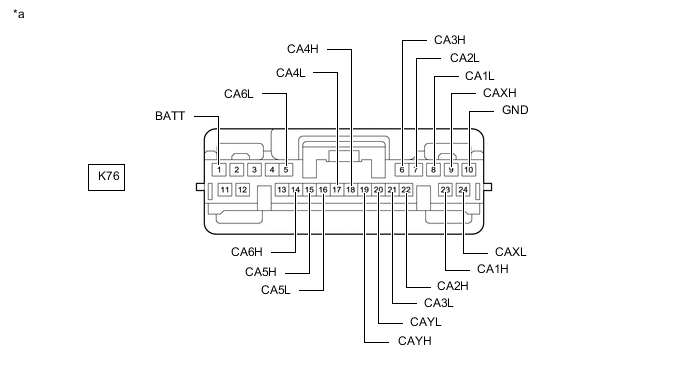
*a Front view of wire harness connector
(to Central Gateway ECU (Network Gateway ECU))
- -
-
-
STEERING SENSOR
-
Disconnect the cable from the negative (-) battery terminal.
-
Disconnect the K71 steering sensor connector.
-
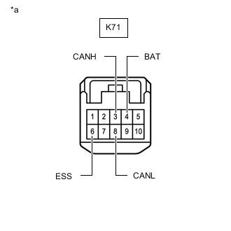
*a Front view of wire harness connector
(to Steering Sensor)
Measure the resistance according to the value(s) in the table below.
-
-
ECM (for A25A-FKS)
Refer to Terminals of ECU.
-
Disconnect the cable from the negative (-) battery terminal.
-
Disconnect the A24 ECM connector.
-
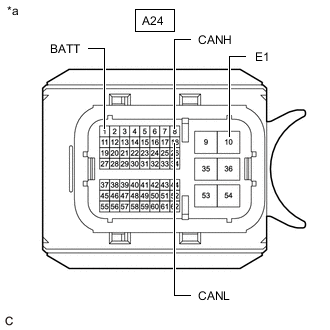
*a Front view of wire harness connector
(to ECM)
Measure the resistance according to the value(s) in the table below.
-
-
ECM (for 2GR-FKS)
Refer to Terminals of ECU.
-
Disconnect the cable from the negative (-) battery terminal.
-
Disconnect the A23 and C96 ECM connectors.
-
Measure the resistance according to the value(s) in the table below.
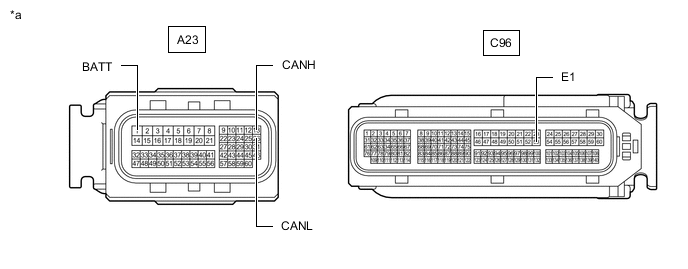
*a Front view of wire harness connector
(to ECM)
- -
-
-
ECM (for 2AR-FE)
Refer to Terminals of ECU.
-
Disconnect the cable from the negative (-) battery terminal.
-
Disconnect the A22 and C58 ECM connectors.
-
Measure the resistance according to the value(s) in the table below.
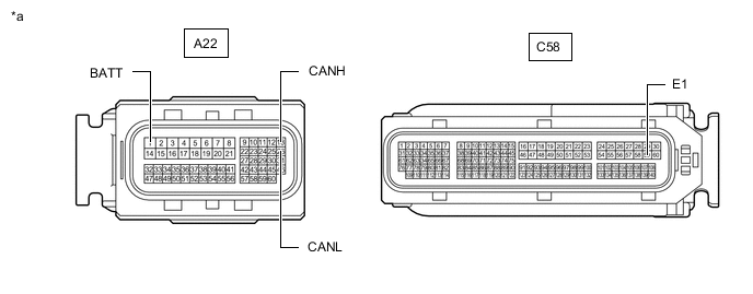
*a Front view of wire harness connector
(to ECM)
- -
-
-
BRAKE ACTUATOR ASSEMBLY
Refer to Terminals of ECU.
-
Disconnect the cable from the negative (-) battery terminal.
-
Disconnect the A34 brake actuator assembly connector.
-
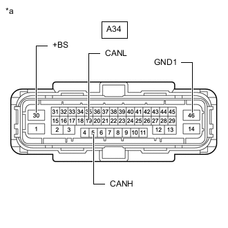
*a Front view of wire harness connector
(to Brake Actuator Assembly)
Measure the resistance according to the value(s) in the table below.
-
-
RACK AND PINION POWER STEERING GEAR ASSEMBLY
Refer to Terminals of ECU.
-
Disconnect the cable from the negative (-) battery terminal.
-
Disconnect the C71 rack and pinion power steering gear assembly connector.
-
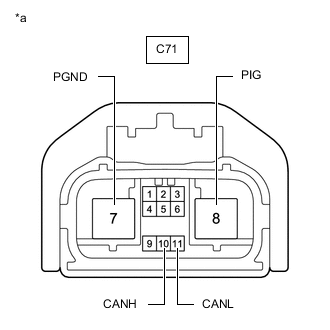
*a Front view of wire harness connector
(to Rack and Pinion Power Steering Gear Assembly)
Measure the resistance according to the value(s) in the table below.
-
-
COMBINATION METER ASSEMBLY
Refer to Terminals of ECU.
-
Disconnect the cable from the negative (-) battery terminal.
-
Disconnect the K21 combination meter assembly connector.
-
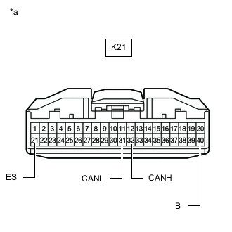
*a Front view of wire harness connector
(to Combination Meter Assembly)
Measure the resistance according to the value(s) in the table below.
-
-
METER MIRROR SUB-ASSEMBLY (w/ Headup Display System)
Refer to Terminals of ECU.
-
Disconnect the cable from the negative (-) battery terminal.
-
Disconnect the p1 meter mirror sub-assembly connector.
-
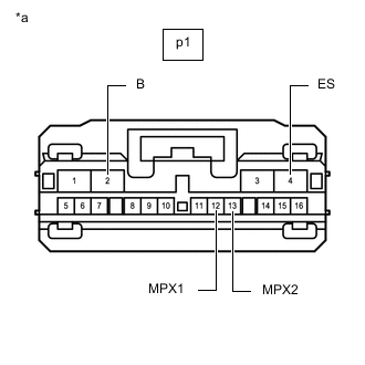
*a Front view of wire harness connector
(to Meter Mirror Sub-assembly)
Measure the resistance according to the value(s) in the table below.
-
-
MAIN BODY ECU (MULTIPLEX NETWORK BODY ECU)
Refer to Terminals of ECU.
-
Disconnect the cable from the negative (-) battery terminal.
-
Disconnect the K52 main body ECU (multiplex network body ECU) connector.
-
Measure the resistance according to the value(s) in the table below.
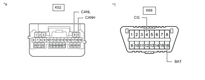
*1 DLC3 - - *a Front view of wire harness connector
(to Main Body ECU (Multiplex Network Body ECU))
- -
-
-
CERTIFICATION ECU (SMART KEY ECU ASSEMBLY) (w/ Smart Entry and Start System)
Refer to Terminals of ECU.
-
Disconnect the cable from the negative (-) battery terminal.
-
Disconnect the K62 certification ECU (smart key ECU assembly) connector.
-
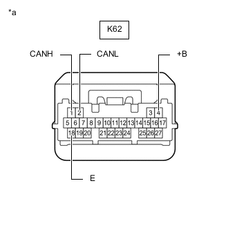
*a Front view of wire harness connector
(to Certification ECU (Smart Key ECU Assembly))
Measure the resistance according to the value(s) in the table below.
-
-
AIRBAG SENSOR ASSEMBLY
Refer to Terminals of ECU.
-
Disconnect the cable from the negative (-) battery terminal.
-
Disconnect the K73 airbag sensor assembly connector.
-
Measure the resistance according to the value(s) in the table below.
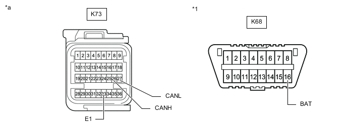
*1 DLC3 - - *a Front view of wire harness connector
(to Airbag Sensor Assembly)
- -
-
-
AIR CONDITIONING AMPLIFIER ASSEMBLY
Refer to Terminals of ECU.
-
Disconnect the cable from the negative (-) battery terminal.
-
Disconnect the K54 air conditioning amplifier assembly connector.
-
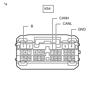
*a Front view of wire harness connector
(to Air Conditioning Amplifier Assembly)
Measure the resistance according to the value(s) in the table below.
-
-
RADIO AND DISPLAY RECEIVER ASSEMBLY (w/ Radio and Display Type)
Refer to Terminals of ECU.
-
for Audio and Visual System
-
for Navigation System
-
Disconnect the cable from the negative (-) battery terminal.
-
Disconnect the K2 radio and display receiver assembly connector.
-
Measure the resistance according to the value(s) in the table below.
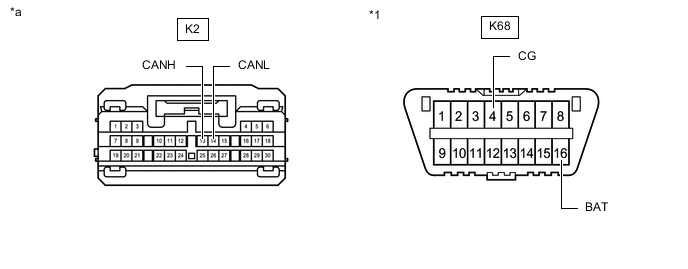
*1 DLC3 - - *a Front view of wire harness connector
(to Radio and Display Receiver Assembly)
- -
-
-
MULTIPLEX TILT AND TELESCOPIC ECU (w/ Power Tilt and Power Telescopic System)
Refer to Terminals of ECU.
-
Disconnect the cable from the negative (-) battery terminal.
-
Disconnect the K72 multiplex tilt and telescopic ECU connector.
-
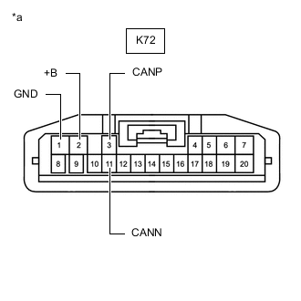
*a Front view of wire harness connector
(to Multiplex Tilt and Telescopic ECU)
Measure the resistance according to the value(s) in the table below.
-
*1: for LHD
-
*2: for RHD
-
-
-
POSITION CONTROL ECU ASSEMBLY RH (w/ Seat Position Memory System)
Refer to Terminals of ECU.
-
Disconnect the cable from the negative (-) battery terminal.
-
Disconnect the a10 and a12 position control ECU assembly RH connectors.
-
Measure the resistance according to the value(s) in the table below.
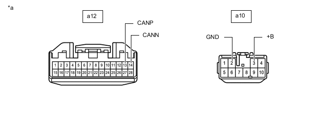
*a Front view of wire harness connector
(to Position Control ECU Assembly RH)
- -
-
-
OUTER MIRROR CONTROL ECU ASSEMBLY (FOR DRIVER SIDE) (w/ Seat Position Memory System)
Refer to Terminals of ECU.
-
Disconnect the cable from the negative (-) battery terminal.
-
Disconnect the N9 outer mirror control ECU assembly (for driver side) connector.
-
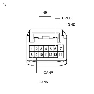
*a Front view of wire harness connector
(to Outer Mirror Control ECU Assembly (for Driver Side))
Measure the resistance according to the value(s) in the table below.
-
-
OUTER MIRROR CONTROL ECU ASSEMBLY (FOR FRONT PASSENGER SIDE) (w/ Seat Position Memory System)
Refer to Terminals of ECU.
-
Disconnect the cable from the negative (-) battery terminal.
-
Disconnect the O8 outer mirror control ECU assembly (for front passenger side) connector.
-

*a Front view of wire harness connector
(to Outer Mirror Control ECU Assembly (for Front Passenger Side))
Measure the resistance according to the value(s) in the table below.
-
-
HEADLIGHT ECU SUB-ASSEMBLY LH
Refer to Terminals of ECU.
-
Disconnect the cable from the negative (-) battery terminal.
-
Disconnect the A10 headlight ECU sub-assembly LH connector.
-
Measure the resistance according to the value(s) in the table below.
*1 DLC3 - - *a Front view of wire harness connector
(to Headlight ECU Sub-assembly LH)
- -
-
-
HEADLIGHT ECU SUB-ASSEMBLY RH
Refer to Terminals of ECU.
-
Disconnect the cable from the negative (-) battery terminal.
-
Disconnect the A11 headlight ECU sub-assembly RH connector.
-
Measure the resistance according to the value(s) in the table below.

*1 DLC3 - - *a Front view of wire harness connector
(to Headlight ECU Sub-assembly RH)
- -
-
-
FORWARD RECOGNITION CAMERA (w/ Toyota Safety Sense)
Refer to Terminals of ECU.
-
Disconnect the cable from the negative (-) battery terminal.
-
Disconnect the V6 forward recognition camera connector.
-
Measure the resistance according to the value(s) in the table below.
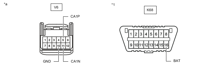
*1 DLC3 - - *a Front view of wire harness connector
(to Forward Recognition Camera)
- -
-
-
MILLIMETER WAVE RADAR SENSOR ASSEMBLY (w/ Toyota Safety Sense)
Refer to Terminals of ECU.
-
for 2AR-FE, w/ Dynamic Radar Cruise Control System
-
for A25A-FKS, w/ Dynamic Radar Cruise Control System
-
Disconnect the cable from the negative (-) battery terminal.
-
Disconnect the A30 millimeter wave radar sensor assembly connector.
-
Measure the resistance according to the value(s) in the table below.
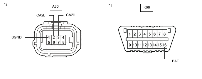
*1 DLC3 - - *a Front view of wire harness connector
(to Millimeter Wave Radar Sensor Assembly)
- -
-
-
CLEARANCE WARNING ECU ASSEMBLY (w/ TOYOTA Parking Assist-sensor System)
Refer to Terminals of ECU.
-
Disconnect the cable from the negative (-) battery terminal.
-
Disconnect the R39 clearance warning ECU assembly connector.
-
Measure the resistance according to the value(s) in the table below.
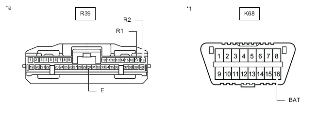
*1 DLC3 - - *a Front view of wire harness connector
(to Clearance Warning ECU Assembly)
- -
-
-
BLIND SPOT MONITOR SENSOR RH (w/ Blind Spot Monitor System)
Refer to Terminals of ECU.
-
Disconnect the cable from the negative (-) battery terminal.
-
Disconnect the W5 blind spot monitor sensor RH connector.
-
Measure the resistance according to the value(s) in the table below.
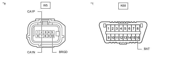
*1 DLC3 - - *a Front view of wire harness connector
(to Blind Spot Monitor Sensor RH)
- -
-
-
REAR TELEVISION CAMERA ASSEMBLY (w/ Parking Assist Monitor System)
Refer to Terminals of ECU.
-
Disconnect the cable from the negative (-) battery terminal.
-
Disconnect the m3 rear television camera assembly connector.
-
Measure the resistance according to the value(s) in the table below.
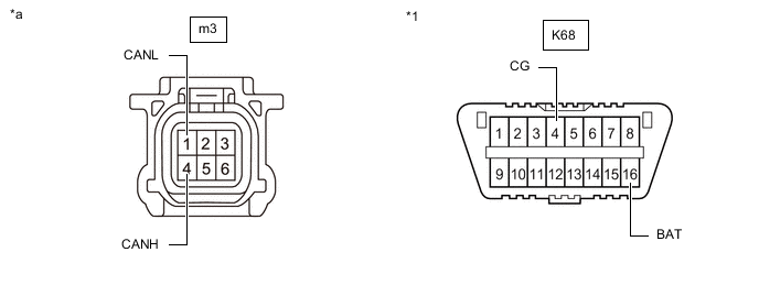
*1 DLC3 - - *a Front view of wire harness connector
(to Rear Television Camera Assembly)
- -
-
-
TIRE PRESSURE WARNING ECU AND RECEIVER (w/ Tire Pressure Warning System)
Refer to Terminals of ECU.
-
Disconnect the cable from the negative (-) battery terminal.
-
Disconnect the R9 tire pressure warning ECU and receiver connector.
-
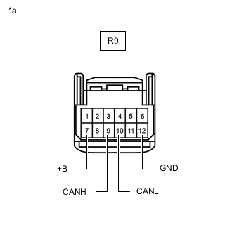
*a Front view of wire harness connector
(to Tire Pressure Warning ECU and Receiver)
Measure the resistance according to the value(s) in the table below.
-
-
OCCUPANT DETECTION ECU (w/ Occupant Classification System)
Refer to Terminals of ECU.
-
Disconnect the cable from the negative (-) battery terminal.
-
Disconnect the a20 occupant detection ECU connector.
-
Measure the resistance according to the value(s) in the table below.
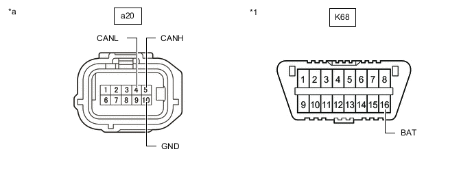
*1 DLC3 - - *a Front view of wire harness connector
(to Occupant Detection ECU)
- -
-