CLEARANCE WARNING ECU(for RHD) REMOVAL
CAUTION / NOTICE / HINT
The necessary procedures (adjustment, calibration, initialization, or registration) that must be performed after parts are removed and installed, or replaced during clearance warning ECU assembly removal/installation are shown below.
| Replaced Part or Performed Procedure | Necessary Procedures | Effect/Inoperative Function When Necessary Procedures are not Performed | Link |
|---|---|---|---|
| Disconnect cable from negative battery terminal | Perform steering sensor zero point calibration | Lane departure alert system (w/ Steering Control) | |
| Pre-collision system | |||
| Memorize steering angle neutral point | Parking assist monitor system | ||
| Replacement of clearance warning ECU assembly | Adjust TOYOTA parking assist-sensor system | TOYOTA parking assist-sensor system |
CAUTION:
Some of these service operations affect the SRS airbag system. Read the precautionary notices concerning the SRS airbag system before servicing.
PROCEDURE
-
REMOVE LOWER NO. 1 INSTRUMENT PANEL AIRBAG ASSEMBLY
-
REMOVE NO. 3 INSTRUMENT PANEL TO COWL BRACE SUB-ASSEMBLY
-
REMOVE ECU INTEGRATION BOX RH
-
REMOVE CLEARANCE WARNING ECU ASSEMBLY
-
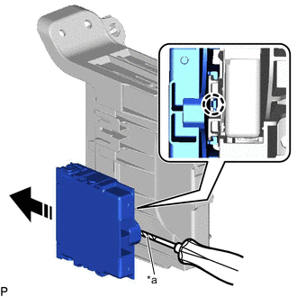
*a Protective Tape 
Remove in this Direction Using a screwdriver with its tip wrapped with protective tape, disengage the claw and remove the clearance warning ECU assembly as shown in the illustration.
Note
-
If the ECU integration box is deformed or damaged, replace it.
-
Do not bend the claw more than necessary.
-
-