NAVIGATION SYSTEM AVC-LAN Circuit
DESCRIPTION
Each unit of the navigation system connected to the AVC-LAN (communication bus) transmits signals via AVC-LAN communication.
If a short to +B or short to ground occurs in an AVC-LAN communication line, the navigation system will not function normally because communication is not possible.
WIRING DIAGRAM
Figure 1. for 6 Speakers
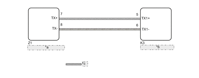
| *a | Cooler Control Switch Assembly |
| *b | Radio and Display Receiver Assembly |
| *c | AVC-LAN Communication Line |
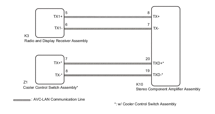
Figure 2. for 9 Speakers
CAUTION / NOTICE / HINT
Note
-
Depending on the parts that are replaced during vehicle inspection or maintenance, performing initialization, registration or calibration may be needed. Refer to Precaution for Navigation System.
-
When replacing the radio and display receiver assembly, always replace it with a new one. If a radio and display receiver assembly which was installed to another vehicle is used, the following may occur:
-
A communication malfunction DTC may be stored.
-
The radio and display receiver assembly may not operate normally.
Tech Tips
The radio and display receiver assembly is the master unit.
PROCEDURE
-
CHECK MODEL
-
Choose the model to be inspected.
Result Result Proceed to for 6 Speakers A for 9 Speakers B
B 
INSPECT RADIO AND DISPLAY RECEIVER ASSEMBLY Click here
A 
-
-
INSPECT RADIO AND DISPLAY RECEIVER ASSEMBLY
-
Remove the radio and display receiver assembly.
-
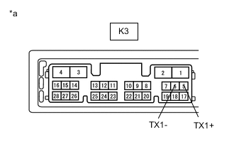
*a Component without harness connected
(Radio and Display Receiver Assembly)
Measure the resistance according to the value(s) in the table below.
Standard Resistance Tester Connection Condition Specified Condition K3-5 (TX1+) - K3-6 (TX1-) Always 60 to 80 Ω Result Proceed to OK NG
NG 
REPLACE RADIO AND DISPLAY RECEIVER ASSEMBLY Click here
OK
-
-
CHECK HARNESS AND CONNECTOR (AVC-LAN CIRCUIT)
-
Disconnect the K3 radio and display receiver assembly connector.
-
Disconnect the Z1 cooler control switch assembly connector.
-
Measure the resistance according to the value(s) in the table below.
Standard Resistance Tester Connection Condition Specified Condition Z1-7 (TX+) - K3-5 (TX1+) Always Below 1 Ω Z1-8 (TX-) - K3-6 (TX1-) Always Below 1 Ω Z1-7 (TX+) or K3-5 (TX1+) - Body ground Always 10 kΩ or higher Z1-8 (TX-) or K3-6 (TX1-) - Body ground Always 10 kΩ or higher Result Proceed to OK NG
NG
REPAIR OR REPLACE HARNESS OR CONNECTOR
OK
-
-
INSPECT MALFUNCTIONING PARTS
-
Disconnect and reconnect each slave unit one by one until the master unit returns to normal.
Tech Tips
-
Check all slave units.
-
If disconnecting a slave unit causes the master unit to return to normal, the slave unit is defective and should be replaced.
OK Master unit returns to normal. Result Proceed to OK NG -
OK
REPLACE MALFUNCTIONING PARTS
NG
REPLACE RADIO AND DISPLAY RECEIVER ASSEMBLY Click here
-
-
INSPECT RADIO AND DISPLAY RECEIVER ASSEMBLY
-
Remove the radio and display receiver assembly.
-

*a Component without harness connected
(Radio and Display Receiver Assembly)
Measure the resistance according to the value(s) in the table below.
Standard Resistance Tester Connection Condition Specified Condition K3-5 (TX1+) - K3-6 (TX1-) Always 60 to 80 Ω Result Proceed to OK NG
NG
REPLACE RADIO AND DISPLAY RECEIVER ASSEMBLY Click here
OK
-
-
CHECK HARNESS AND CONNECTOR (AVC-LAN CIRCUIT)
-
Disconnect the K3 radio and display receiver assembly connector.
-
Disconnect the K10 stereo component amplifier assembly connector.
-
Disconnect the Z1 cooler control switch assembly connector. (w/ Cooler Control Switch Assembly)
-
Measure the resistance according to the value(s) in the table below.
Standard Resistance Tester Connection Condition Specified Condition K3-5 (TX1+) - K10-8 (TX+) Always Below 1 Ω K3-6 (TX1-) - K10-7 (TX-) Always Below 1 Ω K10-20 (TXD+) - Z1-7 (TX+)* Always Below 1 Ω K10-19 (TXD-) - Z1-8 (TX-)* Always Below 1 Ω K3-5 (TX1+) or K10-8 (TX+) - Body ground Always 10 kΩ or higher K3-6 (TX1-) or K10-7 (TX-) - Body ground Always 10 kΩ or higher K10-20 (TXD+) or Z1-7 (TX+) - Body ground* Always 10 kΩ or higher K10-19 (TXD-) or Z1-8 (TX-) - Body ground* Always 10 kΩ or higher
-
*: w/ Cooler Control Switch Assembly
Result Proceed to OK NG -
NG
REPAIR OR REPLACE HARNESS OR CONNECTOR
OK
-
-
INSPECT MALFUNCTIONING PARTS
-
Disconnect and reconnect each slave unit one by one until the master unit returns to normal.
Tech Tips
-
Check all slave units.
-
If disconnecting a slave unit causes the master unit to return to normal, the slave unit is defective and should be replaced.
OK Master unit returns to normal. Result Proceed to OK NG -
OK
REPLACE MALFUNCTIONING PARTS
NG
REPLACE RADIO AND DISPLAY RECEIVER ASSEMBLY Click here
-