NAVIGATION SYSTEM Speaker Circuit
DESCRIPTION
-
If there is a short in a speaker circuit, the radio and display receiver assembly detects it and stops output to the speakers.
Thus sound cannot be heard from the speakers even if there is no malfunction in the radio and display receiver assembly or speakers.
for 6 Speakers
-
If there is a short in a speaker circuit, the stereo component amplifier assembly detects it and stops output to the speakers.
Thus sound cannot be heard from the speakers even if there is no malfunction in the stereo component amplifier assembly or speakers.
for 9 Speakers
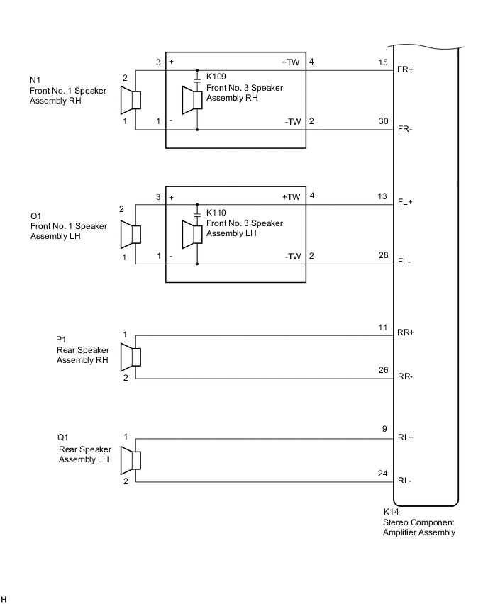
WIRING DIAGRAM
Figure 1. for 6 Speakers
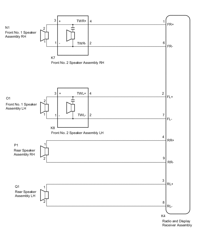
Figure 2. for 9 Speakers
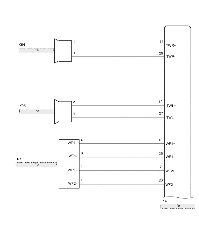
| *a | Front No. 2 Speaker Assembly RH |
| *b | Rear Stereo Component Speaker Assembly |
| *c | Stereo Component Amplifier Assembly |
CAUTION / NOTICE / HINT
Note
-
Depending on the parts that are replaced during vehicle inspection or maintenance, performing initialization, registration or calibration may be needed. Refer to Precaution for Navigation System.
-
When replacing the radio and display receiver assembly, always replace it with a new one. If a radio and display receiver assembly which was installed to another vehicle is used, the following may occur:
-
A communication malfunction DTC may be stored.
-
The radio and display receiver assembly may not operate normally.
PROCEDURE
-
CHECK MODEL
-
Choose the model to be inspected.
Result Result Proceed to for 6 Speakers A for 9 Speakers B
B 
CHECK SPEAKER (OPERATION CHECK) Click here
A 
-
-
CHECK SPEAKER (OPERATION CHECK)
-
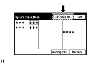
Enter the "System Check Mode" screen. Refer to Check Speaker in Operation Check.
-
Perform the operation check above and determine the speaker that is not operating.
Result Not Operating Speaker Proceed to Front No. 1 speaker assembly or front No. 2 speaker assembly A Rear speaker assembly B Tech Tips
If sound cannot be heard from any speaker, inspect all of them.
B
CHECK HARNESS AND CONNECTOR (RADIO AND DISPLAY RECEIVER ASSEMBLY - REAR SPEAKER ASSEMBLY) Click here
A
-
-
CHECK HARNESS AND CONNECTOR (RADIO AND DISPLAY RECEIVER ASSEMBLY - FRONT NO. 1 SPEAKER ASSEMBLY - FRONT NO. 2 SPEAKER ASSEMBLY)
-
Disconnect the K4 radio and display receiver assembly connector.
-
Disconnect the N1 and O1 front No. 1 speaker assembly connectors.
-
Disconnect the K7 and K8 front No. 2 speaker assembly connectors.
-
Measure the resistance according to the value(s) in the table below.
Standard Resistance Tester Connection Condition Specified Condition K4-1 (FR+) - K7-4 (TWR+) Always Below 1 Ω K4-6 (FR-) - K7-2 (TWR-) Always Below 1 Ω K4-2 (FL+) - K8-4 (TWL+) Always Below 1 Ω K4-7 (FL-) - K8-2 (TWL-) Always Below 1 Ω N1-2 - K7-3 (+) Always Below 1 Ω N1-1 - K7-1 (-) Always Below 1 Ω O1-2 - K8-3 (+) Always Below 1 Ω O1-1 - K8-1 (-) Always Below 1 Ω K4-1 (FR+) or K7-4 (TWR+) - Body ground Always 10 kΩ or higher K4-6 (FR-) or K7-2 (TWR-) - Body ground Always 10 kΩ or higher K4-2 (FL+) or K8-4 (TWL+) - Body ground Always 10 kΩ or higher K4-7 (FL-) or K8-2 (TWL-) - Body ground Always 10 kΩ or higher N1-2 or K7-3 (+) - Body ground Always 10 kΩ or higher N1-1 or K7-1 (-) - Body ground Always 10 kΩ or higher O1-2 or K8-3 (+) - Body ground Always 10 kΩ or higher O1-1 or K8-1 (-) - Body ground Always 10 kΩ or higher Result Proceed to OK NG
NG 
REPAIR OR REPLACE HARNESS OR CONNECTOR
OK
-
-
INSPECT FRONT NO. 1 SPEAKER ASSEMBLY
-
Remove the front No. 1 speaker assembly.
-
Inspect the front No. 1 speaker assembly.
Result Proceed to OK NG
NG
REPLACE FRONT NO. 1 SPEAKER ASSEMBLY Click here
OK
-
-
REPLACE FRONT NO. 2 SPEAKER ASSEMBLY
-
Remove the front No. 2 speaker assembly.
-
Inspect the front No. 2 speaker assembly.
OK Malfunction disappears. Result Proceed to OK NG
OK
END
NG
PROCEED TO NEXT SUSPECTED AREA SHOWN IN PROBLEM SYMPTOMS TABLE Click here
-
-
CHECK HARNESS AND CONNECTOR (RADIO AND DISPLAY RECEIVER ASSEMBLY - REAR SPEAKER ASSEMBLY)
-
Disconnect the K4 radio and display receiver assembly connector.
-
Disconnect the Q1 and P1 rear speaker assembly connectors.
-
Measure the resistance according to the value(s) in the table below.
Standard Resistance Tester Connection Condition Specified Condition K4-4 (RR+) - P1-1 Always Below 1 Ω K4-9 (RR-) - P1-2 Always Below 1 Ω K4-3 (RL+) - Q1-1 Always Below 1 Ω K4-8 (RL-) - Q1-2 Always Below 1 Ω K4-4 (RR+) or P1-1 - Body ground Always 10 kΩ or higher K4-9 (RR-) or P1-2 - Body ground Always 10 kΩ or higher K4-3 (RL+) or Q1-1 - Body ground Always 10 kΩ or higher K4-8 (RL-) or Q1-2 - Body ground Always 10 kΩ or higher Result Proceed to OK NG
NG
REPAIR OR REPLACE HARNESS OR CONNECTOR
OK
-
-
INSPECT REAR SPEAKER ASSEMBLY
-
Remove the rear speaker assembly.
-
Inspect the rear speaker assembly.
Result Proceed to OK NG
OK
PROCEED TO NEXT SUSPECTED AREA SHOWN IN PROBLEM SYMPTOMS TABLE Click here
NG
REPLACE REAR SPEAKER ASSEMBLY Click here
-
-
CHECK SPEAKER (OPERATION CHECK)
-
Enter the "System Check Mode" screen. Refer to Check Speaker in Operation Check.
-
Perform the operation check above and determine the speaker that is not operating.
Result Not Operating Speaker Proceed to Front No. 1 speaker assembly or front No. 3 speaker assembly A Front No. 2 speaker assembly B Rear speaker assembly C Rear stereo component speaker assembly D Tech Tips
If sound cannot be heard from any speaker, inspect all of them.
B
CHECK HARNESS AND CONNECTOR (STEREO COMPONENT AMPLIFIER ASSEMBLY - FRONT NO. 2 SPEAKER ASSEMBLY) Click here
C
CHECK HARNESS AND CONNECTOR (STEREO COMPONENT AMPLIFIER ASSEMBLY - REAR SPEAKER ASSEMBLY) Click here
D
CHECK HARNESS AND CONNECTOR (STEREO COMPONENT AMPLIFIER ASSEMBLY - REAR STEREO COMPONENT SPEAKER ASSEMBLY) Click here
A
-
-
CHECK HARNESS AND CONNECTOR (STEREO COMPONENT AMPLIFIER ASSEMBLY - FRONT NO. 1 SPEAKER ASSEMBLY - FRONT NO. 3 SPEAKER ASSEMBLY)
-
Disconnect the K14 stereo component amplifier assembly connector.
-
Disconnect the N1 and O1 front No. 1 speaker assembly connectors.
-
Disconnect the K109 and K110 front No. 3 speaker assembly connectors.
-
Measure the resistance according to the value(s) in the table below.
Standard Resistance Tester Connection Condition Specified Condition K14-15 (FR+) - K109-4 (+TW) Always Below 1 Ω K14-30 (FR-) - K109-2 (-TW) Always Below 1 Ω K14-13 (FL+) - K110-4 (+TW) Always Below 1 Ω K14-28 (FL-) - K110-2 (-TW) Always Below 1 Ω N1-2 - K109-3 (+) Always Below 1 Ω N1-1 - K109-1 (-) Always Below 1 Ω O1-2 - K110-3 (+) Always Below 1 Ω O1-1 - K110-1 (-) Always Below 1 Ω K14-15 (FR+) or K109-4 (+TW) - Body ground Always 10 kΩ or higher K14-30 (FR-) or K109-2 (-TW) - Body ground Always 10 kΩ or higher K14-13 (FL+) or K110-4 (+TW) - Body ground Always 10 kΩ or higher K14-28 (FL-) or K110-2 (-TW) - Body ground Always 10 kΩ or higher N1-2 or K109-3 (+) - Body ground Always 10 kΩ or higher N1-1 or K109-1 (-) - Body ground Always 10 kΩ or higher O1-2 or K110-3 (+) - Body ground Always 10 kΩ or higher O1-1 or K110-1 (-) - Body ground Always 10 kΩ or higher Result Proceed to OK NG
NG
REPAIR OR REPLACE HARNESS OR CONNECTOR
OK
-
-
INSPECT FRONT NO. 1 SPEAKER ASSEMBLY
-
Remove the front No. 1 speaker assembly.
-
Inspect the front No. 1 speaker assembly.
Result Proceed to OK NG
NG
REPLACE FRONT NO. 1 SPEAKER ASSEMBLY Click here
OK
-
-
REPLACE FRONT NO. 3 SPEAKER ASSEMBLY
-
Remove the front No. 3 speaker assembly.
-
Inspect the front No. 3 speaker assembly.
OK Malfunction disappears. Result Proceed to OK NG
OK
END
NG
PROCEED TO NEXT SUSPECTED AREA SHOWN IN PROBLEM SYMPTOMS TABLE Click here
-
-
CHECK HARNESS AND CONNECTOR (STEREO COMPONENT AMPLIFIER ASSEMBLY - FRONT NO. 2 SPEAKER ASSEMBLY)
-
Disconnect the K14 stereo component amplifier assembly connector.
-
Disconnect the K94 and K95 front No. 2 speaker assembly connectors.
-
Measure the resistance according to the value(s) in the table below.
Standard Resistance Tester Connection Condition Specified Condition K14-14 (TWR+) - K94-2 Always Below 1 Ω K14-29 (TWR-) - K94-1 Always Below 1 Ω K14-12 (TWL+) - K95-2 Always Below 1 Ω K14-27 (TWL-) - K95-1 Always Below 1 Ω K14-14 (TWR+) or K94-2 - Body ground Always 10 kΩ or higher K14-29 (TWR-) or K94-1 - Body ground Always 10 kΩ or higher K14-12 (TWL+) or K95-2 - Body ground Always 10 kΩ or higher K14-27 (TWL-) or K95-1 - Body ground Always 10 kΩ or higher Result Proceed to OK NG
NG
REPAIR OR REPLACE HARNESS OR CONNECTOR
OK
-
-
INSPECT FRONT NO. 2 SPEAKER ASSEMBLY
-
Remove the front No. 2 speaker assembly.
-
Inspect the front No. 2 speaker assembly.
Result Proceed to OK NG
OK
PROCEED TO NEXT SUSPECTED AREA SHOWN IN PROBLEM SYMPTOMS TABLE Click here
NG
REPLACE FRONT NO. 2 SPEAKER ASSEMBLY Click here
-
-
CHECK HARNESS AND CONNECTOR (STEREO COMPONENT AMPLIFIER ASSEMBLY - REAR SPEAKER ASSEMBLY)
-
Disconnect the K14 stereo component amplifier assembly connector.
-
Disconnect the P1 and Q1 rear speaker assembly connectors.
-
Measure the resistance according to the value(s) in the table below.
Standard Resistance Tester Connection Condition Specified Condition K14-11 (RR+) - P1-1 Always Below 1 Ω K14-26 (RR-) - P1-2 Always Below 1 Ω K14-9 (RL+) - Q1-1 Always Below 1 Ω K14-24 (RL-) - Q1-2 Always Below 1 Ω K14-11 (RR+) or P1-1 - Body ground Always 10 kΩ or higher K14-26 (RR-) or P1-2 - Body ground Always 10 kΩ or higher K14-9 (RL+) or Q1-1 - Body ground Always 10 kΩ or higher K14-24 (RL-) or Q1-2 - Body ground Always 10 kΩ or higher Result Proceed to OK NG
NG
REPAIR OR REPLACE HARNESS OR CONNECTOR
OK
-
-
INSPECT REAR SPEAKER ASSEMBLY
-
Remove the rear speaker assembly.
-
Inspect the rear speaker assembly.
Result Proceed to OK NG
OK
PROCEED TO NEXT SUSPECTED AREA SHOWN IN PROBLEM SYMPTOMS TABLE Click here
NG
REPLACE REAR SPEAKER ASSEMBLY Click here
-
-
CHECK HARNESS AND CONNECTOR (STEREO COMPONENT AMPLIFIER ASSEMBLY - REAR STEREO COMPONENT SPEAKER ASSEMBLY)
-
Disconnect the K14 stereo component amplifier assembly connector.
-
Disconnect the R1 rear stereo component speaker assembly connector.
-
Measure the resistance according to the value(s) in the table below.
Standard Resistance Tester Connection Condition Specified Condition K14-10 (WF1+) - R1-4 (WF1+) Always Below 1 Ω K14-25 (WF1-) - R1-3 (WF1-) Always Below 1 Ω K14-8 (WF2+) - R1-2 (WF2+) Always Below 1 Ω K14-23 (WF2-) - R1-1 (WF2-) Always Below 1 Ω K14-10 (WF1+) or R1-4 (WF1+) - Body ground Always 10 kΩ or higher K14-25 (WF1-) or R1-3 (WF1-) - Body ground Always 10 kΩ or higher K14-8 (WF2+) or R1-2 (WF2+) - Body ground Always 10 kΩ or higher K14-23 (WF2-) or R1-1 (WF2-) - Body ground Always 10 kΩ or higher Result Proceed to OK NG
NG
REPAIR OR REPLACE HARNESS OR CONNECTOR
OK
-
-
INSPECT REAR STEREO COMPONENT SPEAKER ASSEMBLY
-
Remove the rear stereo component speaker assembly.
-
Inspect the rear stereo component speaker assembly.
Result Proceed to OK NG
OK
PROCEED TO NEXT SUSPECTED AREA SHOWN IN PROBLEM SYMPTOMS TABLE Click here
NG
REPLACE REAR STEREO COMPONENT SPEAKER ASSEMBLY Click here
-