PROCEDURE
- Click here
INSTALL NO. 4 ANTENNA CORD SUB-ASSEMBLY (w/ Digital Audio Broadcasting Antenna)
-
Engage the 9 clamps to install the No. 4 antenna cord sub-assembly.
-
Connect the connector.
-
- Click here
INSTALL NO. 2 ANTENNA CORD SUB-ASSEMBLY
Tip:Butyl tape and adhesive tape are not available as supply parts. If these pieces of tape still have enough adhesion to secure the No. 2 antenna cord sub-assembly to the roof headlining assembly, reuse them. If the adhesive tape and/or the butyl tape is no longer sticky, apply new tape following the procedure below.
-
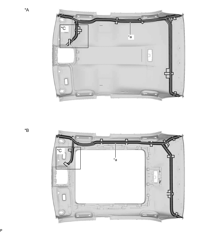
*A for Normal Roof *B for Panoramic Moon Roof *C w/ Television Antenna - - *a Marking - - 
Butyl tape - - Apply new butyl tape.
-
Remove the old butyl tape from the roof headlining assembly.
-
Prepare an appropriate amount of new butyl tape.
Tip:Be careful not to touch the adhesive surface.
-
Apply the butyl tape to the roof headlining assembly while aligning the tape with the markings on the roof headlining assembly.
-
Peel off the release paper from the butyl tape.
-
-
w/o Television Antenna:
-
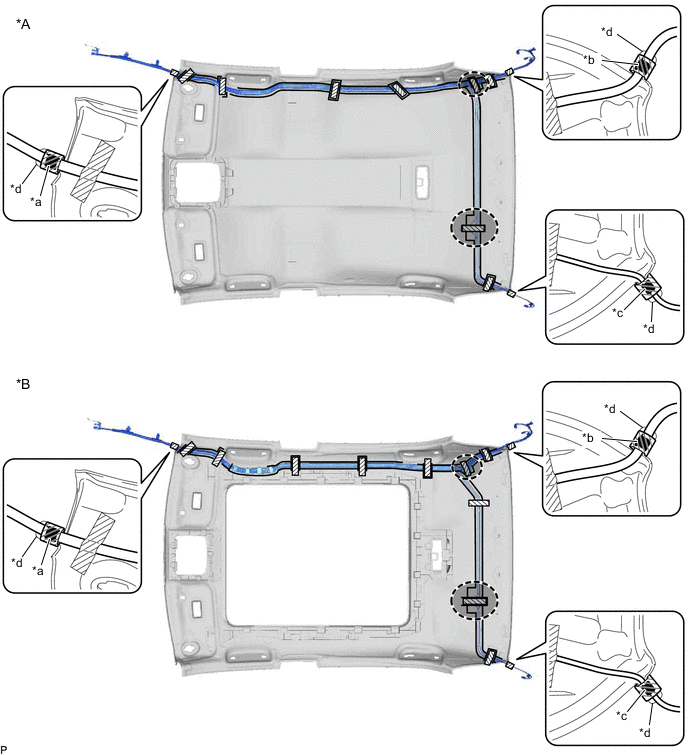
*A for Normal Roof *B for Panoramic Moon Roof *a Marking Tape (A) *b Marking Tape (B) *c Marking Tape (C) *d Protrusion 
Adhesive Tape 
Adjustment Area Align the marking tape (A) on the No. 2 antenna cord sub-assembly with the protrusion on the front of the roof headlining assembly and wrap tape around the No. 2 antenna cord sub-assembly and protrusion of the roof headlining assembly.
-
Align the marking tape (B) on the No. 2 antenna cord sub-assembly with the protrusion on the rear of the roof headlining assembly and wrap tape around the No. 2 antenna cord sub-assembly and protrusion of the roof headlining assembly.
-
Align the marking tape (C) on the No. 2 antenna cord sub-assembly with the protrusion on the rear of the roof headlining assembly and wrap tape around the No. 2 antenna cord sub-assembly and protrusion of the roof headlining assembly.
-
Install the No. 2 antenna cord sub-assembly to the roof headlining assembly.
Note:
-
Make sure that there are no gaps between the roof headlining assembly and No. 2 antenna cord sub-assembly, and that the No. 2 antenna cord sub-assembly is not twisted.
-
Make sure the No. 2 antenna cord sub-assembly is securely installed. If any part of the No. 2 antenna cord sub-assembly is loose, it will cause an abnormal noise.
Tip:Secure the extra length of the No. 2 antenna cord sub-assembly in the adjustment area.
-
-
Apply the adhesive tape as shown in the illustration to secure the No. 2 antenna cord sub-assembly.
-
-
w/ Television Antenna:
-

*A for Normal Roof *B for Panoramic Moon Roof *a Marking Tape (A) *b Marking Tape (B) *c Marking Tape (C) *d Marking Tape (D) *e Protrusion *f Marking Adhesive Tape Adjustment Area Align the marking tape (A) on the No. 2 antenna cord sub-assembly with the protrusion on the front of the roof headlining assembly and wrap tape around the No. 2 antenna cord sub-assembly and protrusion of the roof headlining assembly.
-
Align the marking tape (B) on the No. 2 antenna cord sub-assembly with the protrusion on the rear of the roof headlining assembly and wrap tape around the No. 2 antenna cord sub-assembly and protrusion of the roof headlining assembly.
-
Align the marking tape (C) on the No. 2 antenna cord sub-assembly with the protrusion on the rear of the roof headlining assembly and wrap tape around the No. 2 antenna cord sub-assembly and protrusion of the roof headlining assembly.
-
Align the marking tape (D) on the No. 2 antenna cord sub-assembly with the marking on the roof headlining assembly and secure the No. 2 antenna cord sub-assembly with the adhesive tape as shown in the illustration.
-
Install the No. 2 antenna cord sub-assembly to the roof headlining assembly.
Note:
-
Make sure that there are no gaps between the roof headlining assembly and No. 2 antenna cord sub-assembly, and that the No. 2 antenna cord sub-assembly is not twisted.
-
Make sure the No. 2 antenna cord sub-assembly is securely installed. If any part of the No. 2 antenna cord sub-assembly is loose, it will cause an abnormal noise.
Tip:Secure the extra length of the No. 2 antenna cord sub-assembly in the adjustment area.
-
-
Apply the adhesive tape as shown in the illustration to secure the No. 2 antenna cord sub-assembly.
-
-
- Click here
INSTALL ROOF HEADLINING ASSEMBLY
- Click here
INSTALL ANTENNA CORD SUB-ASSEMBLY (for LHD)
-
Engage the 6 clamps to install the antenna cord sub-assembly.
-
- Click here
INSTALL NO. 3 HEATER TO REGISTER DUCT SUB-ASSEMBLY (for LHD)
- Click here
INSTALL NO. 2 SIDE DEFROSTER NOZZLE DUCT (for LHD)
- Click here
INSTALL ANTENNA CORD SUB-ASSEMBLY (for RHD)
-
Engage the 6 clamps to install the antenna cord sub-assembly.
-
- Click here
INSTALL NO. 1 HEATER TO REGISTER DUCT SUB-ASSEMBLY (for RHD)
- Click here
INSTALL METER MIRROR SUB-ASSEMBLY (for RHD)
w/ Headup Display:
- Click here
INSTALL DEFROSTER NOZZLE ASSEMBLY (for RHD)
w/ Headup Display:
- Click here
INSTALL NO. 2 SIDE DEFROSTER NOZZLE DUCT (for RHD)
w/ Headup Display:
- Click here
INSTALL NO. 1 SIDE DEFROSTER NOZZLE DUCT (for RHD)
- Click here
INSTALL INSTRUMENT PANEL SAFETY PAD SUB-ASSEMBLY