RADIO ANTENNA CORD REMOVAL
CAUTION / NOTICE / HINT
The necessary procedures (adjustment, calibration, initialization, or registration) that must be performed after parts are removed and installed, or replaced during antenna cord sub-assembly removal/installation are shown below.
| Replaced Part or Performed Procedure | Necessary Procedure | Effect/Inoperative Function When Necessary Procedures are not Performed | Link |
|---|---|---|---|
| Disconnect cable from negative battery terminal | Perform steering sensor zero point calibration | Lane departure alert system (w/ Steering Control) | |
| Pre-collision system | |||
| Memorize steering angle neutral point | Parking assist monitor system |
CAUTION:
Some of these service operations affect the SRS airbag system. Read the precautionary notices concerning the SRS airbag system before servicing.
PROCEDURE
-
REMOVE INSTRUMENT PANEL SAFETY PAD SUB-ASSEMBLY
-
REMOVE NO. 2 SIDE DEFROSTER NOZZLE DUCT (for LHD)
-
REMOVE NO. 3 HEATER TO REGISTER DUCT SUB-ASSEMBLY (for LHD)
-
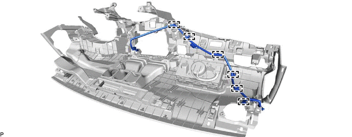
REMOVE ANTENNA CORD SUB-ASSEMBLY (for LHD)
-
Disengage the 6 clamps and remove the antenna cord sub-assembly.
-
-
REMOVE NO. 1 SIDE DEFROSTER NOZZLE DUCT (for RHD)
-
REMOVE NO. 2 SIDE DEFROSTER NOZZLE DUCT (for RHD)
w/ Headup Display:
-
REMOVE DEFROSTER NOZZLE ASSEMBLY (for RHD)
w/ Headup Display:
-
REMOVE METER MIRROR SUB-ASSEMBLY (for RHD)
w/ Headup Display:
-
REMOVE NO. 1 HEATER TO REGISTER DUCT SUB-ASSEMBLY (for RHD)
-
REMOVE ANTENNA CORD SUB-ASSEMBLY (for RHD)
-
Disengage the 6 clamps and remove the antenna cord sub-assembly.

-
-
REMOVE ROOF HEADLINING ASSEMBLY
-
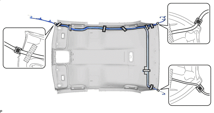
REMOVE NO. 2 ANTENNA CORD SUB-ASSEMBLY
-
w/o Television Antenna:
-
Remove the adhesive tape from the roof headlining assembly.
for Normal Roof:

Adhesive Tape - - for Moon Roof:
Adhesive Tape - - for Panoramic Moon Roof:
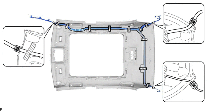
Adhesive Tape - - -
Remove the No. 2 antenna cord sub-assembly from the roof headlining assembly.
-
-
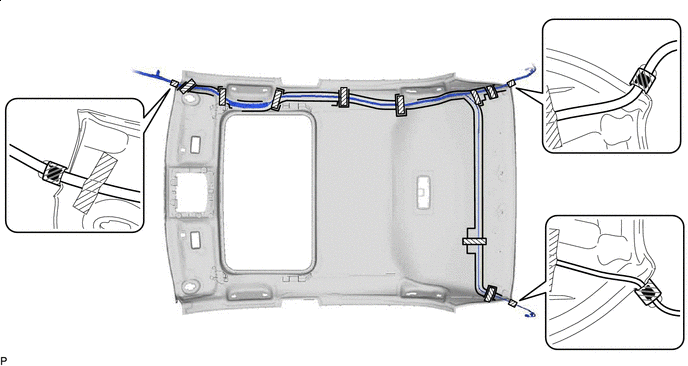
w/ Television Antenna:
-
Remove the adhesive tape from the roof headlining assembly.
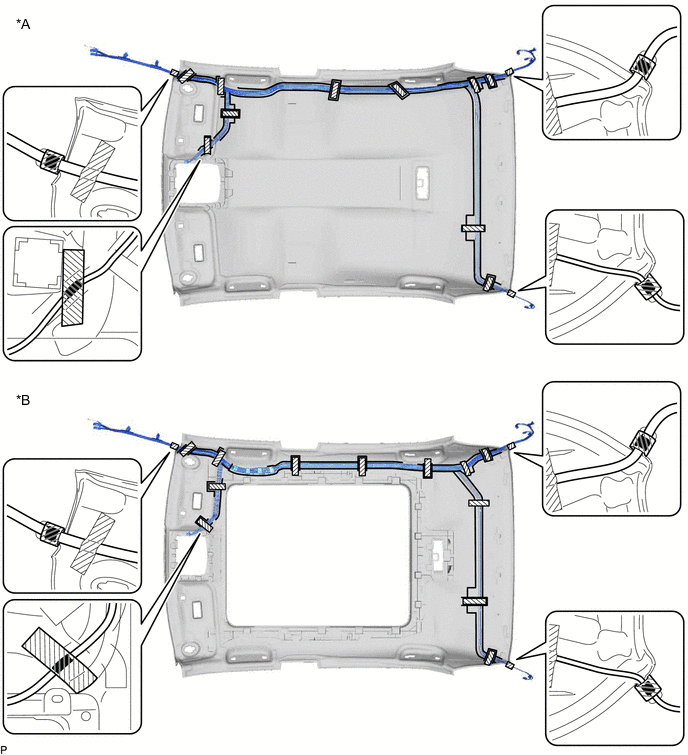
*A for Normal Roof *B for Panoramic Moon Roof Adhesive Tape - - -
Remove the No. 2 antenna cord sub-assembly from the roof headlining assembly.
-
-
-
REMOVE NO. 4 ANTENNA CORD SUB-ASSEMBLY (w/ Digital Audio Broadcasting Antenna)
-
Disconnect the connector.
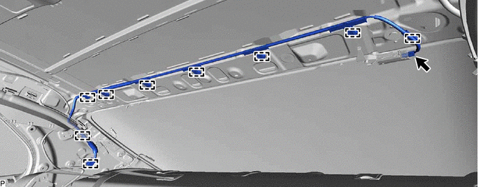
-
Disengage the 9 clamps to remove the No. 4 antenna cord sub-assembly.
-