RADIO RECEIVER REMOVAL
PROCEDURE
-
PRECAUTION (w/o Navigation System)
Note
-
When replacing the radio and display receiver assembly, always replace it with a new one. If a radio and display receiver assembly which was installed to another vehicle is used, the following may occur:
-
A communication malfunction DTC may be stored.
-
The radio and display receiver assembly may not operate normally.
-
-
PRECAUTION (w/ Navigation System)
Note
-
When replacing the radio and display receiver assembly or navigation ECU, always replace it with a new one. If a radio and display receiver assembly or navigation ECU which was installed to another vehicle is used, the following may occur:
-
A communication malfunction DTC may be stored.
-
The radio and display receiver assembly or navigation ECU may not operate normally.
-
After replacing the radio and display receiver assembly, if "New software is not compatible with the system. Contact your dealer." is displayed on the multi-display, update the software of the navigation ECU.
-
-
CHANGE POWER TILT AND POWER TELESCOPIC STEERING COLUMN SYSTEM SETTINGS (for Power Tilt and Power Telescopic Steering Column)
-
REMOVE NO. 1 METER HOOD CLUSTER
-
REMOVE NO. 2 INSTRUMENT PANEL GARNISH SUB-ASSEMBLY
-
REMOVE LOWER INSTRUMENT PANEL FINISH PANEL ASSEMBLY
-
REMOVE NO. 3 INSTRUMENT PANEL REGISTER ASSEMBLY
-
REMOVE RADIO AND DISPLAY RECEIVER ASSEMBLY WITH BRACKET
-
for Manual Tilt and Manual Telescopic Steering Column:
-
Release the tilt and telescopic lever and fully extend and lower the steering column assembly.
-
Lock the tilt and telescopic lever.
-
-
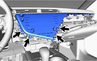
Remove the 4 bolts.
-
Disengage the 4 clips in the order shown in the illustration.
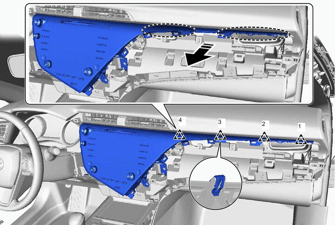

Place Hand Here 
Remove in this Direction -
Disengage the 7 clips as shown in the illustration.
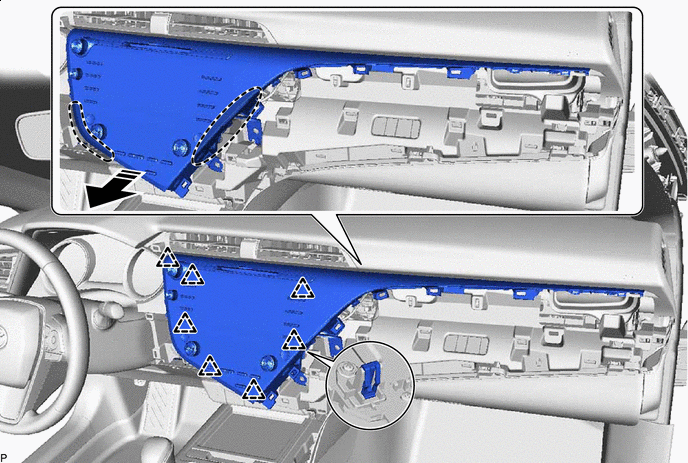
Place Hand Here Remove in this Direction -
Disengage the 2 guides as shown in the illustration.
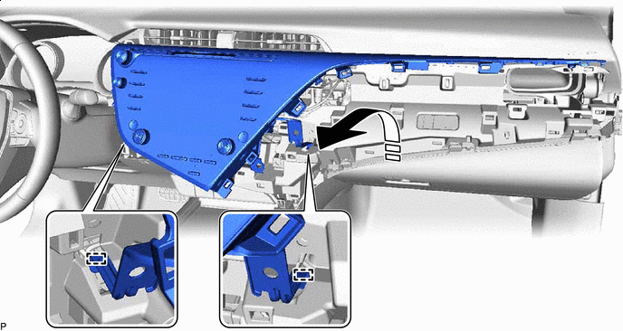
Remove in this Direction - - -
Disconnect each connector and remove the radio and display receiver assembly with bracket.
-
-
REMOVE MULTI-MEDIA MODULE WIRE
-
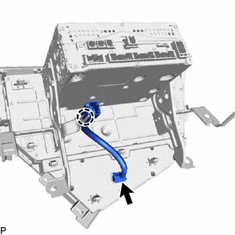
Disconnect the connector.
-
Disengage the claw to remove the multi-media module wire.
-
-
DISCONNECT NAVIGATION ECU WITH WIRE (w/ Navigation System)
-
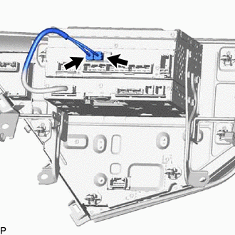
Disconnect the 2 connectors to disconnect the navigation ECU with wire.
-
-
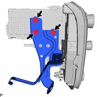
REMOVE NO. 1 RADIO RECEIVER BRACKET
-
w/o Navigation System:
-
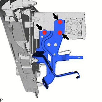
Remove the 3 screws and No. 1 radio receiver bracket.
-
-
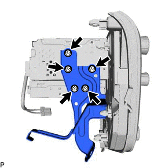
w/ Navigation System:
-
Remove the 5 screws and No. 1 radio receiver bracket.
-
-
-
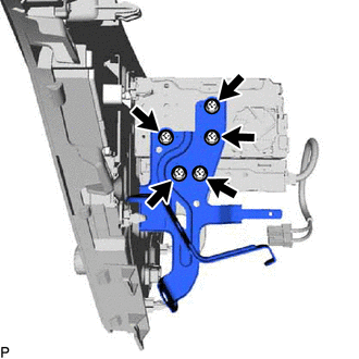
REMOVE NO. 2 RADIO RECEIVER BRACKET
-
w/o Navigation System:
-
Remove the 3 screws and No. 2 radio receiver bracket.
-
-
w/ Navigation System:
-
Remove the 5 screws and No. 2 radio receiver bracket.
-
-
-
REMOVE NAVIGATION ECU WITH WIRE (w/ Navigation System)
-
REMOVE RADIO AND DISPLAY RECEIVER ASSEMBLY