AUDIO AND VISUAL SYSTEM, Diagnostic DTC:B1324
| DTC Code | DTC Name |
|---|---|
| B1324 | Lost Communication with Meter |
DESCRIPTION
This DTC is stored when a communication error occurs between the radio and display receiver assembly and combination meter assembly.
| DTC No. | Detection Item | DTC Detection Condition | Trouble Area |
|---|---|---|---|
| B1324 | Lost Communication with Meter | CAN reception error |
|
Tech Tips
The radio and display receiver assembly is the master unit.
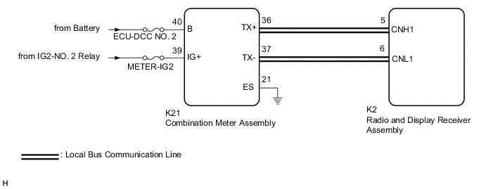
WIRING DIAGRAM
CAUTION / NOTICE / HINT
Note
-
Depending on the parts that are replaced during vehicle inspection or maintenance, performing initialization, registration or calibration may be needed. Refer to Precaution for Audio and Visual System.
-
When replacing the radio and display receiver assembly, always replace it with a new one. If a radio and display receiver assembly which was installed to another vehicle is used, the following may occur:
-
A communication malfunction DTC may be stored.
-
The radio and display receiver assembly may not operate normally.
-
Inspect the fuses for circuits related to this system before performing the following procedure.
PROCEDURE
-
CHECK HARNESS AND CONNECTOR (COMBINATION METER ASSEMBLY POWER SOURCE)
-
Disconnect the K21 combination meter assembly connector.
-
Measure the resistance according to the value(s) in the table below.
Standard Resistance Tester Connection Condition Specified Condition K21-21 (ES) - Body ground Always Below 1 Ω -
Measure the voltage according to the value(s) in the table below.
Standard Voltage Tester Connection Condition Specified Condition K21-40 (B) - Body ground Always 11 to 14 V K21-39 (IG+) - Body ground Ignition switch ON 11 to 14 V Result Proceed to OK NG
NG 
REPAIR OR REPLACE HARNESS OR CONNECTOR
OK 
-
-
CHECK HARNESS AND CONNECTOR
-
Disconnect the cable from the negative (-) battery terminal.
-
Disconnect the K21 combination meter assembly connector.
-
Measure the resistance according to the value(s) in the table below.
Standard Resistance Tester Connection Condition Specified Condition K21-36 (TX+) - K21-37 (TX-) Cable disconnected from negative (-) battery terminal 108 to 132 Ω Result Proceed to OK NG
OK
REPLACE COMBINATION METER ASSEMBLY Click here
NG
-
-
CHECK HARNESS AND CONNECTOR (RADIO AND DISPLAY RECEIVER ASSEMBLY - COMBINATION METER ASSEMBLY)
-
Disconnect the K2 radio and display receiver assembly connector.
-
Disconnect the K21 combination meter assembly connector.
-
Measure the resistance according to the value(s) in the table below.
Standard Resistance Tester Connection Condition Specified Condition K2-5 (CNH1) - K21-36 (TX+) Always Below 1 Ω K2-6 (CNL1) - K21-37 (TX-) Always Below 1 Ω K2-5 (CNH1) or K21-36 (TX+) - Body ground Always 10 kΩ or higher K2-6 (CNL1) or K21-37 (TX-) - Body ground Always 10 kΩ or higher Result Proceed to OK NG
OK
REPLACE RADIO AND DISPLAY RECEIVER ASSEMBLY Click here
NG
REPAIR OR REPLACE HARNESS OR CONNECTOR
-