STEERING GEAR INSTALLATION

PROCEDURE
-
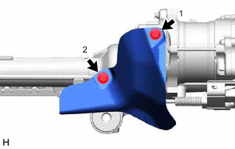
INSTALL STEERING GEAR HEAT INSULATOR (for LHD)
-
for 2GR-FKS:
-
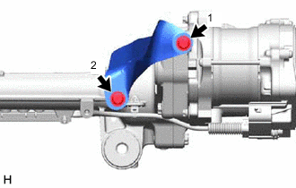
Install the steering gear heat insulator to the rack and pinion power steering gear assembly with the 2 bolts in the order shown in the illustration.
- Torque:
- 8.0 N*m { 82 kgf*cm, 71 in.*lbf }
-
-
-
INSTALL TIE ROD ASSEMBLY LH
-
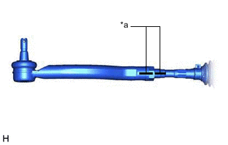
*a Matchmark Install the lock nut and tie rod assembly LH to the rack and pinion power steering gear assembly until the matchmarks are aligned.
Tech Tips
After adjusting the toe-in, tighten the lock nut.
-
-
INSTALL TIE ROD ASSEMBLY RH
Tech Tips
Perform the same procedure as for the LH side.
-
INSTALL RACK AND PINION POWER STEERING GEAR ASSEMBLY
-
Install the rack and pinion power steering gear assembly to the front frame assembly with the 4 bolts and 4 new nuts.
- Torque:
- 88 N*m { 897 kgf*cm, 65 ft.*lbf }
Note
Because the nut has its own stopper, do not turn the nut. Tighten the bolt with the nut secured.
-
-
INSTALL FRONT STABILIZER BAR WITH BRACKET (for A25A-FKS)
-
Install the front stabilizer bar with the 2 front stabilizer links, front No. 1 stabilizer bracket LH, front No. 1 stabilizer bracket sub-assembly RH and 2 front No. 1 stabilizer bar bushings to the front frame assembly.
-
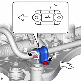
*a Arrow 
Front of the Vehicle Install the front No. 1 stabilizer bracket LH to the front frame assembly with the 2 bolts.
- Torque:
- 44 N*m { 449 kgf*cm, 32 ft.*lbf }
Note
-
Make sure to install the front No. 1 stabilizer bracket LH with its arrow facing the front of the vehicle.
-
Temporarily tighten the bolt (B) and then fully tighten the 2 bolts in the order of (A) and (B).
-
*a Arrow Front of the Vehicle Install the front No. 1 stabilizer bracket sub-assembly RH to the front frame assembly with the 2 bolts.
- Torque:
- 44 N*m { 449 kgf*cm, 32 ft.*lbf }
Note
-
Make sure to install the front No. 1 stabilizer bracket sub-assembly RH with its arrow facing the front of the vehicle.
-
Temporarily tighten the bolt (B) and then fully tighten the 2 bolts in the order of (A) and (B).
-
-
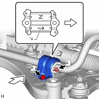
INSTALL FRONT STABILIZER BAR WITH BRACKET (for 2AR-FE, 2GR-FKS)
-
Install the front stabilizer bar with the 2 front stabilizer links, front No. 1 stabilizer bracket LH, front No. 1 stabilizer bracket RH and 2 front No. 1 stabilizer bar bushings to the front frame assembly.
-
*a Arrow Front of the Vehicle Install the front No. 1 stabilizer bracket LH to the front frame assembly with the 2 bolts.
- Torque:
- 44 N*m { 449 kgf*cm, 32 ft.*lbf }
Note
-
Make sure to install the front No. 1 stabilizer bracket LH with its arrow facing the front of the vehicle.
-
Temporarily tighten the bolt (B) and then fully tighten the 2 bolts in the order of (A) and (B).
-
Install the front No. 1 stabilizer bracket RH to the front frame assembly with the 2 bolts.
Tech Tips
Perform the same procedure as for the LH side.
-
-
INSTALL FRONT FRAME ASSEMBLY
-
REMOVE ENGINE HANGER (for 2GR-FKS)
-
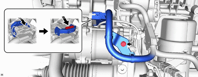
CONNECT WIRE HARNESS (for LHD)
-
Install the wire harness to the rack and pinion power steering gear assembly with the 2 bolts.
- Torque:
- 10 N*m { 102 kgf*cm, 7 ft.*lbf }

-
Connect the wire harness connector to the rack and pinion power steering gear assembly.
Tech Tips
Make sure that the connector is fully inserted before rotating the lock lever to engage the lock.
-
-
CONNECT WIRE HARNESS (for RHD)
-
Install the wire harness to the rack and pinion power steering gear assembly with the bolt.
- Torque:
- 10 N*m { 102 kgf*cm, 7 ft.*lbf }
-
Connect the wire harness connector to the rack and pinion power steering gear assembly.
Tech Tips
Make sure that the connector is fully inserted before rotating the lock lever to engage the lock.
-
-
INSTALL STEERING GEAR HEAT INSULATOR (for LHD)
-
for A25A-FKS:
-
Install the steering gear heat insulator to the rack and pinion power steering gear assembly with the 2 bolts in the order shown in the illustration.
- Torque:
- 8.0 N*m { 82 kgf*cm, 71 in.*lbf }
-
-
-
INSTALL ENGINE ASSEMBLY WITH TRANSAXLE
for 2AR-FE: Click here
for A25A-FKS: Click here
for 2GR-FKS: Click here
-
CONNECT TIE ROD ASSEMBLY LH
-
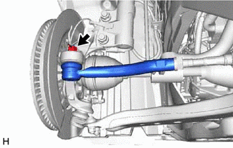
Connect the tie rod assembly LH to the steering knuckle LH with the nut.
- Torque:
- 49 N*m { 500 kgf*cm, 36 ft.*lbf }
Note
-
Do not damage the ball joint dust cover.
-
Further tighten the nut up to 60° if the holes for the cotter pin are not aligned.
-
Install a new cotter pin.
-
-
CONNECT TIE ROD ASSEMBLY RH
Tech Tips
Perform the same procedure as for the LH side.
-
CONNECT STEERING INTERMEDIATE SHAFT ASSEMBLY
-
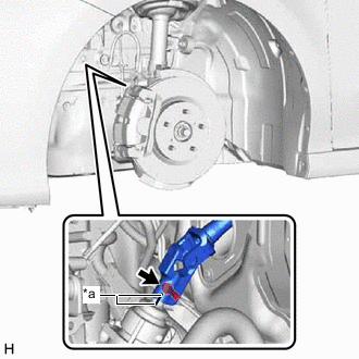
*a Matchmark Align the matchmarks on the steering intermediate shaft assembly and rack and pinion power steering gear assembly.
-
Connect the steering intermediate shaft assembly to the rack and pinion power steering gear assembly.
-
Install a bolt.
- Torque:
- 35 N*m { 357 kgf*cm, 26 ft.*lbf }
-
-
INSTALL NO. 2 ENGINE UNDER COVER ASSEMBLY (for A25A-FKS)
-
INSTALL NO. 1 ENGINE UNDER COVER (for A25A-FKS)
-
INSTALL FRONT WHEEL OPENING EXTENSION PAD LH (for A25A-FKS)
-
INSTALL FRONT WHEEL OPENING EXTENSION PAD RH (for A25A-FKS)
-
INSTALL FRONT WHEELS
-
TORQUE SENSOR ZERO POINT CALIBRATION