STEERING GEAR REMOVAL

CAUTION / NOTICE / HINT
The necessary procedures (adjustment, calibration, initialization, or registration) that must be performed after parts are removed and installed, or replaced during rack and pinion power steering gear assembly removal/installation are shown below.
| Replaced Part or Performed Procedure | Necessary Procedure | Effect/Inoperative Function when Necessary Procedure not Performed | Link |
|---|---|---|---|
| Battery terminal is disconnected/reconnected | Perform steering sensor zero point calibration | Lane departure alert system (w/ Steering Control) | |
| Pre-collision system | |||
| Memorize steering angle neutral point | Parking assist monitor system | ||
| Replacement of ECM | Vehicle Identification Number (VIN) registration | MIL comes on | for 2AR-FE: Click here for A25A-FKS: Click here for 2GR-FKS: Click here |
| Perform code registration (Immobiliser system) | Engine start function | See Service Bulletin for the registration method. | |
|
Inspection After Repair |
|
for 2AR-FE: Click here for A25A-FKS: Click here for 2GR-FKS: Click here |
| Replacement of automatic transaxle assembly |
|
|
for UA80E Initialization: Click here for UA80E Registration: Click here for UB80E Initialization: Click here for UB80E Registration: Click here for U760E Initialization: Click here for U760E Registration: Click here |
| Replacement of ECM (If possible, read the transaxle compensation code from the previous ECM) |
|
||
| Replacement of ECM (If impossible, read the transaxle compensation code from the previous ECM) |
|
||
| Replacement of ECM | Perform code registration (Immobiliser function) |
|
See Service Bulletin for the registration method. |
| Suspension, tires, etc. (The vehicle height changes because of suspension or tire replacement) |
Rear television camera assembly optical axis (Back camera position setting) | Parking assist monitor system | for Initialization: Click here for Calibration: Click here |
| Perform headlight ECU sub-assembly LH initialization | Lighting system (EXT) | ||
| Front wheel alignment adjustment | Perform system variant learning and acceleration sensor zero point calibration. |
|
|
| Rack and pinion power steering gear assembly |
|
|
PROCEDURE
-
PRECAUTION
-
When handling the rack and pinion power steering gear assembly:
-
Do not subject the rack and pinion power steering gear assembly (especially the motor and torque sensor) to any impact. Replace the rack and pinion power steering gear assembly with a new one if subjected to a strong impact.
-
Do not pull the wire harness when moving the rack and pinion power steering gear assembly.
-
When the rack and pinion power steering gear assembly has been replaced, perform torque sensor zero point calibration.
-
-
When disconnecting or reconnecting the connectors:
-
Before disconnecting connectors related to the power steering system, turn the ignition switch to ON, center the steering wheel, turn the ignition switch off, and then disconnect the connectors.
-
Before reconnecting connectors related to the power steering system, ensure that the ignition switch is off. Then center the steering wheel and turn the ignition switch to ON.
Note
Do not turn the ignition switch to ON when the steering wheel is not centered.
-
If the above operations are not carried out properly, the steering center point (zero point) will deviate, which may lead to a difference in steering effort between turning right and left.
Tech Tips
If there is a difference in steering effort between turning right and left, perform torque sensor zero point calibration.
-
-
-
ALIGN FRONT WHEELS FACING STRAIGHT AHEAD
-
SECURE STEERING WHEEL
-
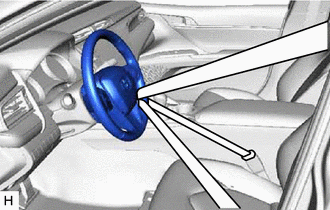
Secure the steering wheel with the seat belt in order to prevent rotation.
Tech Tips
This operation is useful to prevent damage to the spiral cable.
-
-
REMOVE FRONT WHEELS
-
REMOVE FRONT WHEEL OPENING EXTENSION PAD LH (for A25A-FKS)
-
REMOVE FRONT WHEEL OPENING EXTENSION PAD RH (for A25A-FKS)
-
REMOVE NO. 1 ENGINE UNDER COVER (for A25A-FKS)
-
REMOVE NO. 2 ENGINE UNDER COVER ASSEMBLY (for A25A-FKS)
-
SEPARATE STEERING INTERMEDIATE SHAFT ASSEMBLY
-
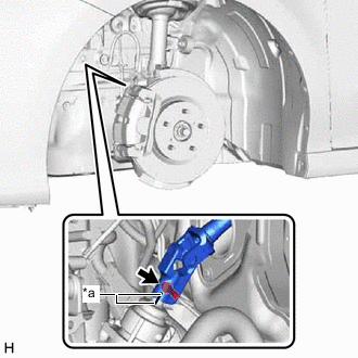
*a Matchmark Remove the bolt and slide the steering intermediate shaft assembly.
Note
Do not separate the steering intermediate shaft assembly from the rack and pinion power steering gear assembly.
-
Put matchmarks on the rack and pinion power steering gear assembly and steering intermediate shaft assembly.
-
Separate the steering intermediate shaft assembly from the rack and pinion power steering gear assembly.
-
-
SEPARATE TIE ROD ASSEMBLY LH
-
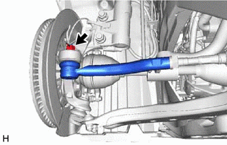
Remove the cotter pin and nut.
-
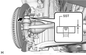
Install SST to the tie rod assembly LH as shown in the illustration.
- SST
- 09960-20010 ( 09961-02060 )
Note
Make sure that the upper ends of the tie rod assembly LH and SST are aligned.
-
Using SST, separate the tie rod assembly LH from the steering knuckle LH as shown in the illustration.
- SST
- 09960-20010 ( 09961-02010 )
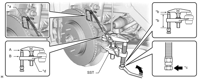
*a String *b Molybdenum Grease Application Area *c Place wrench here *d Center Nut 
Turn - - CAUTION:
Apply molybdenum grease to the threads and end of the SST bolt.
Note
-
Be sure to tighten the string firmly to secure SST to the steering knuckle LH to prevent SST from falling off.
-
Install SST with the center nut so that (A) and (B) shown in the illustration are parallel. Otherwise, the ball joint dust cover may be damaged.
-
Be sure to place the wrench on the part shown in the illustration.
-
Do not damage the front disc brake dust cover.
-
Do not damage the ball joint dust cover.
-
Do not damage the steering knuckle LH.
-
-
SEPARATE TIE ROD ASSEMBLY RH
Tech Tips
Perform the same procedure as for the LH side.
-
REMOVE ENGINE ASSEMBLY WITH TRANSAXLE
for 2AR-FE: Click here
for A25A-FKS: Click here
for 2GR-FKS: Click here
-
REMOVE STEERING GEAR HEAT INSULATOR (for LHD)
-
for A25A-FKS:
-
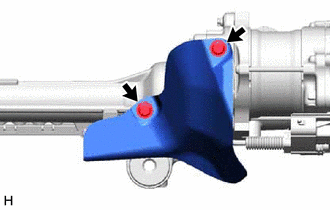
Remove the 2 bolts and steering gear heat insulator from the rack and pinion power steering gear assembly.
-
-
-
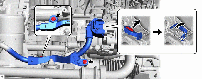
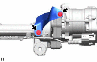
DISCONNECT WIRE HARNESS (for LHD)
-
Disconnect the wire harness connector from the rack and pinion power steering gear assembly.
Tech Tips
Release the lock before rotating the lock lever.
-
Remove the 2 bolts and separate the wire harness from the rack and pinion power steering gear assembly.
-
-
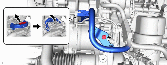
DISCONNECT WIRE HARNESS (for RHD)
-
Disconnect the wire harness connector from the rack and pinion power steering gear assembly.
Tech Tips
Release the lock before rotating the lock lever.
-
Remove the bolt and separate the wire harness from the rack and pinion power steering gear assembly.
-
-
REMOVE FUEL DELIVERY GUARD (for A25A-FKS)
-
INSTALL ENGINE HANGER
for 2AR-FE: Click here
for A25A-FKS: Click here
for 2GR-FKS: Click here
-
REMOVE FRONT FRAME ASSEMBLY
-
REMOVE FRONT STABILIZER BAR WITH BRACKET (for A25A-FKS)
-
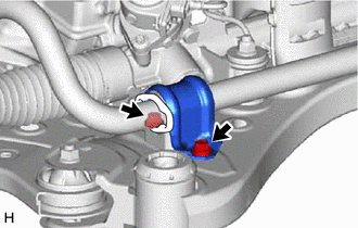
Remove the 2 bolts and separate the front No. 1 stabilizer bracket LH from the front frame assembly.
-
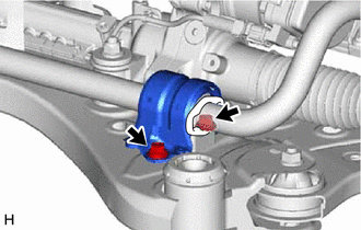
Remove the 2 bolts and separate the front No. 1 stabilizer bracket sub-assembly RH from the front frame assembly.
-
Remove the front stabilizer bar with the 2 front stabilizer links, front No. 1 stabilizer bracket LH, front No. 1 stabilizer bracket sub-assembly RH and 2 front No. 1 stabilizer bar bushings from the front frame assembly.
-
-
REMOVE FRONT STABILIZER BAR WITH BRACKET (for 2AR-FE, 2GR-FKS)
-
Remove the 2 bolts and separate the front No. 1 stabilizer bracket LH from the front frame assembly.
-
Remove the 2 bolts and separate the front No. 1 stabilizer bracket RH from the front frame assembly.
Tech Tips
Perform the same procedure as for the LH side.
-
Remove the front stabilizer bar with the 2 front stabilizer links, front No. 1 stabilizer bracket LH, front No. 1 stabilizer bracket RH and 2 front No. 1 stabilizer bar bushings from the front frame assembly.
-
-
REMOVE RACK AND PINION POWER STEERING GEAR ASSEMBLY
-
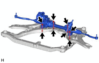
Remove the 4 bolts, 4 nuts and rack and pinion power steering gear assembly from the front frame assembly.
Note
Because the nut has its own stopper, do not turn the nut. Loosen the bolt with the nut secured.
-
-
SECURE RACK AND PINION POWER STEERING GEAR ASSEMBLY
-
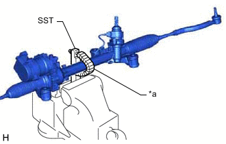
*a Protective Tape Using SST, secure the rack and pinion power steering gear assembly in a vise.
- SST
- 09612-00012
Tech Tips
Wrap SST with protective tape before use.
-
-
REMOVE TIE ROD ASSEMBLY LH
-
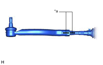
*a Matchmark Put matchmarks on the tie rod assembly LH and rack and pinion power steering gear assembly.
-
Remove the tie rod assembly LH and lock nut.
-
-
REMOVE TIE ROD ASSEMBLY RH
Tech Tips
Perform the same procedure as for the LH side.
-
REMOVE STEERING GEAR HEAT INSULATOR (for LHD)
-
for 2GR-FKS:
-
Remove the 2 bolts and steering gear heat insulator from the rack and pinion power steering gear assembly.
-
-