STEERING PAD SWITCH INSPECTION
PROCEDURE
-
INSPECT STEERING PAD SWITCH ASSEMBLY (Type A)
-
Measure the resistance according to the value(s) in the table below.
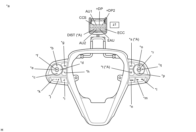
*A w/ Lane Departure Alert System - - *a Component without harness connected
(Steering Pad Switch Assembly)
*b Up *c Down *d Right *e Left *f OK *g Back *h On/off Hook *i Voice *j Volume+ *k Volume- *l Seek+ *m Seek- *n MODE *o +RES *p -SET *q Cruise Control Main *r CANCEL *s Distance Control *t Lane Departure Alert Standard Resistance Tester Connection Condition Specified Condition z1-3 (AU1) - z1-10 (EAU) No switch pushed 95 to 105 kΩ Seek+ switch pushed Below 2.5 Ω Seek- switch pushed 313 to 345 Ω Volume+ switch pushed 950 to 1050 Ω Volume- switch pushed 2955 to 3265 Ω z1-9 (AU2) - z1-10 (EAU) No switch pushed 95 to 105 kΩ MODE switch pushed Below 2.5 Ω On/off hook switch pushed 950 to 1050 Ω Voice switch pushed 2955 to 3265 Ω z1-5 (+DP2) - z1-10 (EAU) No switch pushed 95 to 105 kΩ Left switch pushed Below 2.5 Ω Up switch pushed 313 to 345 Ω Down switch pushed 950 to 1050 Ω Right switch pushed 2955 to 3265 Ω z1-4 (+DP) - z1-10 (EAU) No switch pushed 95 to 105 kΩ OK switch pushed Below 2.5 Ω Back switch pushed 313 to 345 Ω z1-8 (DIST) - z1-12 (ECC)* No switch pushed 1 MΩ or higher Distance control switch pushed Below 2.5 Ω Lane departure alert switch pushed 228 to 252 Ω z1-2 (CCS) - z1-12 (ECC) No switch pushed 1 MΩ or higher Cruise control main switch pushed Below 2.5 Ω CANCEL switch pushed 228 to 252 Ω +RES switch pushed 599 to 661 Ω -SET switch pushed 1463 to 1617 Ω
-
*: w/ Lane Departure Alert System
Tech Tips
If the result is not as specified, replace the steering pad switch assembly.
-
-
Check the illumination.
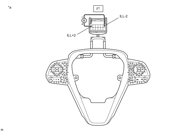
*a Component without harness connected
(Steering Pad Switch Assembly)
- -
-
Connect a positive (+) lead from the battery to terminal z1-1 (ILL+2) and a negative (-) lead to terminal z1-6 (ILL-2) of the steering pad switch assembly connector.
-
Check that the steering pad switch assembly illumination illuminates.
OK The steering pad switch assembly illumination illuminates. Tech Tips
If the result is not as specified, replace the steering pad switch assembly.
-
-
-
INSPECT STEERING PAD SWITCH ASSEMBLY (Type B)
-
Measure the resistance according to the value(s) in the table below.
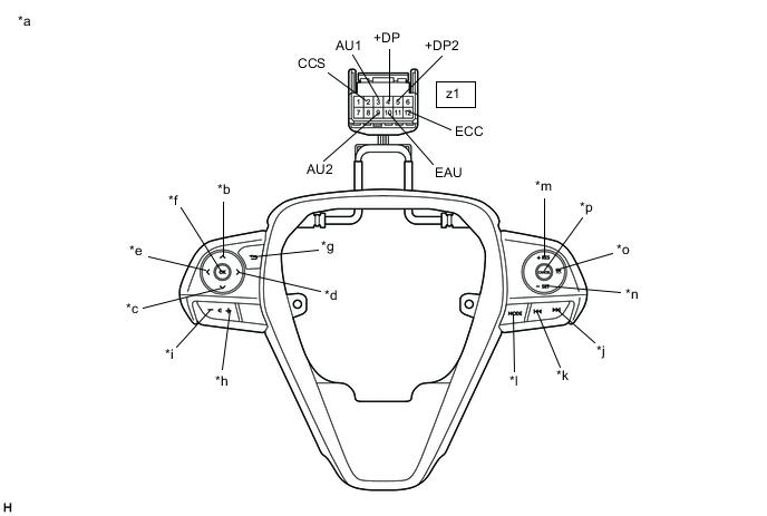
*a Component without harness connected
(Steering Pad Switch Assembly)
*b Up *c Down *d Right *e Left *f OK *g Back *h Volume+ *i Volume- *j Seek+ *k Seek- *l MODE *m +RES *n -SET *o Cruise Control Main *p CANCEL Standard Resistance Tester Connection Condition Specified Condition z1-3 (AU1) - z1-10 (EAU) No switch pushed 95 to 105 kΩ Seek+ switch pushed Below 2.5 Ω Seek- switch pushed 313 to 345 Ω Volume+ switch pushed 950 to 1050 Ω Volume- switch pushed 2955 to 3265 Ω z1-9 (AU2) - z1-10 (EAU) No switch pushed 95 to 105 kΩ MODE switch pushed Below 2.5 Ω z1-5 (+DP2) - z1-10 (EAU) No switch pushed 95 to 105 kΩ Left switch pushed Below 2.5 Ω Up switch pushed 313 to 345 Ω Down switch pushed 950 to 1050 Ω Right switch pushed 2955 to 3265 Ω z1-4 (+DP) - z1-10 (EAU) No switch pushed 95 to 105 kΩ OK switch pushed Below 2.5 Ω Back switch pushed 313 to 345 Ω z1-2 (CCS) - z1-12 (ECC) No switch pushed 1 MΩ or higher Cruise control main switch pushed Below 2.5 Ω CANCEL switch pushed 228 to 252 Ω +RES switch pushed 599 to 661 Ω -SET switch pushed 1463 to 1617 Ω Tech Tips
If the result is not as specified, replace the steering pad switch assembly.
-
Check the illumination.
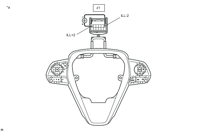
*a Component without harness connected
(Steering Pad Switch Assembly)
- -
-
Connect a positive (+) lead from the battery to terminal z1-1 (ILL+2) and a negative (-) lead to terminal z1-6 (ILL-2) of the steering pad switch assembly connector.
-
Check that the steering pad switch assembly illumination illuminates.
OK The steering pad switch assembly illumination illuminates. Tech Tips
If the result is not as specified, replace the steering pad switch assembly.
-
-