STEERING COLUMN ASSEMBLY(for Power Tilt and Power Telescopic Steering Column) INSTALLATION
PROCEDURE
-
ALIGN FRONT WHEELS FACING STRAIGHT AHEAD
-
INSTALL STEERING COLUMN ASSEMBLY
Note
Make sure that the wire harness is not interfering with the steering column assembly.
-
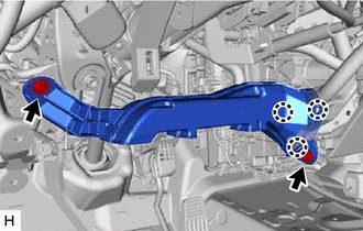
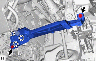
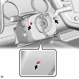
Install the steering column assembly with the bolt and 2 nuts.
- Torque:
- 36 N*m { 367 kgf*cm, 27 ft.*lbf }
-
Connect each connector and engage each wire harness clamp to the steering column assembly.
-
-
INSTALL STEERING INTERMEDIATE SHAFT ASSEMBLY
-
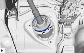
*a Matchmark Align the matchmarks on the steering intermediate shaft assembly and steering column assembly.
-
Install the steering intermediate shaft assembly to the steering column assembly.
-
Install the bolt.
- Torque:
- 35 N*m { 357 kgf*cm, 26 ft.*lbf }
-
Tighten the clamp.
-
-
INSTALL STEERING COLUMN HOLE COVER
-
Install the steering column hole cover with the 2 clips.
-
Install the clip.
-
Return the floor carpet.
-
-
CONNECT STEERING INTERMEDIATE SHAFT ASSEMBLY
-
INSTALL FRONT WHEEL LH (for LHD)
-
INSTALL FRONT WHEEL RH (for RHD)
-
INSTALL NO. 1 AIR DUCT (for LHD)
-
Engage the 3 claws to install a new No. 1 air duct.
-
Install the 2 bolts.
- Torque:
- 9.8 N*m { 100 kgf*cm, 87 in.*lbf }
-
-
INSTALL NO. 1 AIR DUCT (for RHD)
-
Engage the 3 claws to install a new No. 1 air duct.
-
Install the 2 bolts.
- Torque:
- 9.8 N*m { 100 kgf*cm, 87 in.*lbf }
-
-
INSTALL LOWER NO. 1 INSTRUMENT PANEL AIRBAG ASSEMBLY (w/ Driver Side Knee Airbag)
for LHD: Click here
for RHD: Click here
-
INSTALL NO. 1 INSTRUMENT PANEL SUB-ASSEMBLY
w/ Driver Side Knee Airbag: Click here
w/o Driver Side Knee Airbag: : Click here
-
INSTALL LOWER CENTER INSTRUMENT PANEL FINISH PANEL
-
INSTALL NO. 1 METER HOOD CLUSTER
-
CONNECT HOOD LOCK CONTROL LEVER SUB-ASSEMBLY
-
INSTALL NO. 2 METER HOOD CLUSTER
-
INSTALL NO. 1 INSTRUMENT PANEL UNDER COVER SUB-ASSEMBLY
for LHD: Click here
for RHD: Click here
-
INSTALL INSTRUMENT SIDE PANEL
-
CONNECT FRONT DOOR OPENING TRIM WEATHERSTRIP
-
Install the front door opening trim weatherstrip.
Note
After installation, check that the corners fit correctly.
-
-
INSTALL COWL SIDE TRIM SUB-ASSEMBLY
-
INSTALL FRONT DOOR SCUFF PLATE
-
INSTALL TURN SIGNAL SWITCH ASSEMBLY WITH SPIRAL CABLE SUB-ASSEMBLY
Note
-
Do not remove/install the spiral cable with sensor sub-assembly with the battery connected and the engine switch on (IG).
-
Do not rotate the spiral cable with sensor sub-assembly without the steering wheel assembly installed, with the battery connected and the engine switch on (IG).
-
Ensure that the steering wheel assembly is installed and aligned straight when inspecting the steering sensor.
-
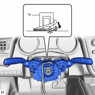
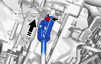
*a Clamp Using pliers, expand the clamp.
-
While holding the clamp expanded, install the turn signal switch assembly with spiral cable sub-assembly to the steering column assembly and engage the claw.
-
Return the clamp to its original position.
-
Connect the connectors to the turn signal switch assembly with spiral cable sub-assembly.
-
-
INSTALL UPPER STEERING COLUMN COVER
-
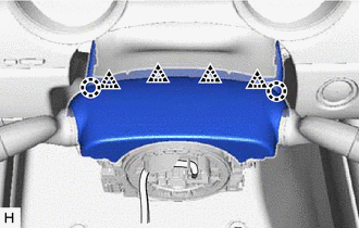
Engage the 2 claws and 4 clips to connect the upper steering column cover.
-
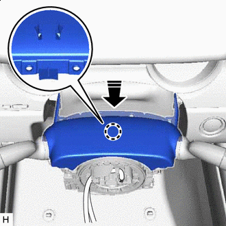

Install in this direction Engage the claw to install the upper steering column cover.
-
-
INSTALL LOWER STEERING COLUMN COVER SUB-ASSEMBLY
-
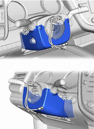
Engage the 2 claws to install the lower steering column cover sub-assembly.
-
Install the 3 screws.
-
-
ALIGN FRONT WHEELS FACING STRAIGHT AHEAD
-
INSPECT AND ADJUST SPIRAL CABLE WITH SENSOR SUB-ASSEMBLY
-
INSTALL STEERING WHEEL ASSEMBLY
-
CHECK STEERING WHEEL CENTER POINT
-
INSTALL HORN BUTTON ASSEMBLY
-
CUSTOMIZE POWER TILT AND POWER TELESCOPIC STEERING COLUMN SYSTEM
-
Set the auto tilt away function setting to the previous condition by changing the customize parameter.
-
-
PERFORM INITIALIZATION AND CALIBRATION (w/ Parking Assist Monitor System)
for Initialization: Click here
for Calibration: Click here