STEERING COLUMN ASSEMBLY(for Power Tilt and Power Telescopic Steering Column) REMOVAL
CAUTION / NOTICE / HINT
The necessary procedures (adjustment, calibration, initialization, or registration) that must be performed after parts are removed and installed, or replaced during steering column assembly removal/installation are shown below.
| Replaced Part or Performed Procedure | Necessary Procedure | Effect/Inoperative Function when Necessary Procedure not Performed | Link |
|---|---|---|---|
| Disconnect cable from negative battery terminal | Perform steering sensor zero point calibration | Lane departure alert system (w/ Steering Control) | |
| Pre-collision system | |||
| Memorize steering angle neutral point | Parking assist monitor system | ||
| Steering sensor |
|
Parking assist monitor system | for Initialization: Click here for Calibration: Click here |
| Steering lock ECU (steering lock actuator or upper bracket assembly)*1 | Perform code registration (Immobiliser function) | Smart Entry and Start System (for Start Function) | See Service Bulletin for the registration method. |
PROCEDURE
-
PRECAUTION
-
CHANGE POWER TILT AND POWER TELESCOPIC STEERING COLUMN SYSTEM SETTINGS
-
Disable the auto tilt away function by changing the customize settings.
Note
Record the current customize setting (whether the auto tilt away function is enabled or disabled) in order to restore the current setting after finishing the operation.
Tech Tips
Performing the above operation causes the auto tilt away function to be disabled when the engine switch is turned off.
-
Turn the engine switch on (IG). Operate the tilt and telescopic switch to fully extend and lower the steering column assembly.
-
-
ALIGN FRONT WHEELS FACING STRAIGHT AHEAD
-
REMOVE HORN BUTTON ASSEMBLY
-
REMOVE STEERING WHEEL ASSEMBLY
-
REMOVE LOWER STEERING COLUMN COVER SUB-ASSEMBLY
Note
Removing the lower steering column cover sub-assembly in the incorrect order will cause the parts to break.
-
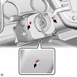
Remove the 3 screws.
-
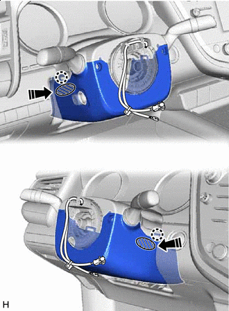

Push Area 
Push in this direction While pressing the push area shown in the illustration to disengage the 2 claws, slightly lower the lower steering column cover sub-assembly.
-
-
REMOVE UPPER STEERING COLUMN COVER
-
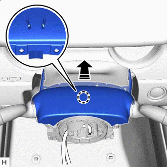
Separate in this direction Disengage the claw and separate the upper steering column cover.
-
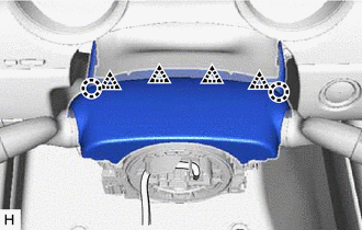
Disengage the 2 claws and 4 clips to remove the upper steering column cover.
-
-
REMOVE TURN SIGNAL SWITCH ASSEMBLY WITH SPIRAL CABLE SUB-ASSEMBLY
Note
-
Do not remove/install the spiral cable with sensor sub-assembly with the battery connected and the engine switch on (IG).
-
Do not rotate the spiral cable with sensor sub-assembly without the steering wheel assembly installed, with the battery connected and the engine switch on (IG).
-
Ensure that the steering wheel assembly is installed and aligned straight when inspecting the steering sensor.
-
Disconnect each connector from the turn signal switch assembly with spiral cable sub-assembly.
-
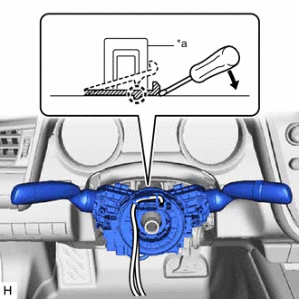
*a Clamp Using pliers, expand the clamp.
-
While holding the clamp expanded, raise the claw using a screwdriver to disengage it, and then remove the turn signal switch assembly with spiral cable sub-assembly from the steering column assembly.
-
-
REMOVE LOWER NO. 1 INSTRUMENT PANEL AIRBAG ASSEMBLY
-
REMOVE NO. 1 AIR DUCT (for LHD)
-
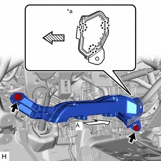
*a View A 
Front Remove the 2 bolts.
-
Disengage the 3 claws to remove the No. 1 air duct.
Note
Be careful not to deform or damage the lower heater case of the air conditioner unit assembly when removing the No. 1 air duct.
-
-
REMOVE NO. 1 AIR DUCT (for RHD)
-
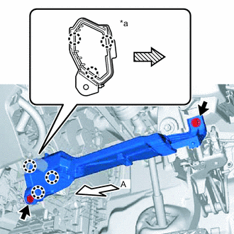
*a View A Front Remove the 2 bolts.
-
Disengage the 3 claws to remove the No. 1 air duct.
Note
Be careful not to deform or damage the lower heater case of the air conditioner unit assembly when removing the No. 1 air duct.
-
-
REMOVE FRONT WHEEL LH (for LHD)
-
REMOVE FRONT WHEEL RH (for RHD)
-
SEPARATE STEERING INTERMEDIATE SHAFT ASSEMBLY
-
REMOVE STEERING COLUMN HOLE COVER
-
Turn back the floor carpet.
-
Remove the clip.
-
Disengage the 2 clips to remove the steering column hole cover.
-
-
REMOVE STEERING INTERMEDIATE SHAFT ASSEMBLY
-
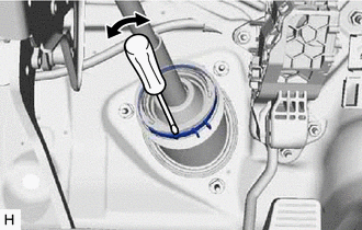
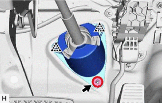
Using a screwdriver, loosen the clamp as shown in the illustration.
-
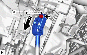
*a Matchmark Remove the bolt and slide the steering intermediate shaft assembly.
Note
Do not remove the steering intermediate shaft assembly from the steering column assembly.
-
Put matchmarks on the steering intermediate shaft assembly and steering column assembly.
-
Remove the steering intermediate shaft assembly from the steering column assembly.
-
-
REMOVE STEERING COLUMN ASSEMBLY
-
Disconnect each connector and disengage each wire harness clamp from the steering column assembly.
-
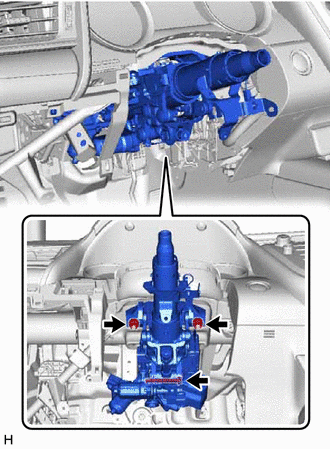
Remove the bolt, 2 nuts and steering column assembly.
-