STEERING COLUMN ASSEMBLY(for Manual Tilt and Manual Telescopic Steering Column) DISASSEMBLY
CAUTION / NOTICE / HINT
Note
w/ Smart Key System:
Before replacing the steering lock actuator assembly, refer to Service Bulletin.
PROCEDURE
-
REMOVE UPPER STEERING COLUMN BRACKET WITH SWITCH ASSEMBLY (w/o Smart Key System)
-
Secure the steering column assembly in a vise between aluminum plates.
Note
Do not overtighten the vise.
-
Using a drill, drill a hole in the 2 steering lock set bolts and insert a screw extractor.
-
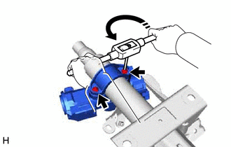
Using the screw extractor, remove the 2 steering lock set bolts, upper steering column clamp and upper steering column bracket with switch assembly.
-
-
REMOVE STEERING LOCK ACTUATOR ASSEMBLY (w/ Smart Key System)
Tech Tips
Perform the same procedure as for the upper steering column bracket with switch assembly (w/o Smart Key System).
-
REMOVE IGNITION SWITCH LOCK CYLINDER ASSEMBLY (w/o Smart Key System)
-
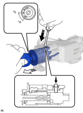
*a LOCK *b ACC 
Push 
Pull Turn the ignition switch to ACC.
-
Insert the tip of a screwdriver into the hole in the upper steering column bracket assembly, as shown in the illustration, and pull out the ignition switch lock cylinder assembly.
-
-
REMOVE UN-LOCK WARNING SWITCH ASSEMBLY (w/o Smart Key System)
-
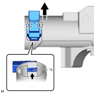
*a Center Part Remove the un-lock warning switch assembly by pushing up the center part and releasing the 2 claws.
Tech Tips
Slide the un-lock warning switch assembly in the direction shown by the arrow in the illustration to remove it.
-
-
REMOVE IGNITION OR STARTER SWITCH ASSEMBLY (w/o Smart Key System)
-
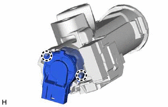
Disengage the 2 claws and remove the ignition or starter switch assembly from the upper steering column bracket assembly.
-