CAUTION / NOTICE / HINT
The necessary procedures (adjustment, calibration, initialization, or registration) that must be performed after parts are removed and installed, or replaced during steering column assembly removal/installation are shown below.
| Replaced Part or Performed Procedure | Necessary Procedure | Effect/Inoperative Function when Necessary Procedure not Performed | Link |
|---|---|---|---|
| Disconnect cable from negative battery terminal | Perform steering sensor zero point calibration | Lane departure alert system (w/ Steering Control) | |
| Pre-collision system | |||
| Memorize steering angle neutral point | Parking assist monitor system | ||
| Steering sensor |
|
Parking assist monitor system | for Initialization:Click here for Calibration:Click here |
| Steering lock ECU (steering lock actuator or upper bracket assembly)*1 | Perform code registration (Immobiliser function) | Smart Entry and Start System (for Start Function) | See Service Bulletin for the registration method. |
PROCEDURE
- Click here
PRECAUTION
- Click here
ALIGN FRONT WHEELS FACING STRAIGHT AHEAD
- Click here
REMOVE HORN BUTTON ASSEMBLY
- Click here
REMOVE STEERING WHEEL ASSEMBLY
- Click here
REMOVE LOWER STEERING COLUMN COVER SUB-ASSEMBLY
Note:Removing the lower steering column cover sub-assembly in the incorrect order will cause the parts to break.
-
Release the tilt and telescopic lever and fully extend and lower the steering column assembly.
-
Lock the tilt and telescopic lever.
-
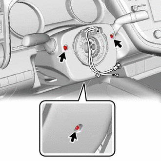
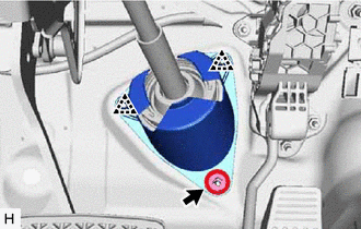
Remove the 3 screws.
-
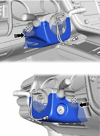

Push Area 
Push in this Direction While pressing the push area shown in the illustration to disengage the 2 claws, slightly lower the lower steering column cover sub-assembly.
-
- Click here
REMOVE UPPER STEERING COLUMN COVER
-
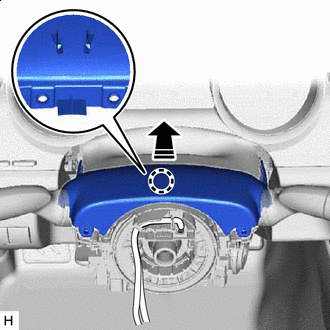
Separate in this direction Disengage the claw and separate the upper steering column cover.
-
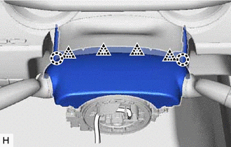
Disengage the 2 claws and 4 clips to remove the upper steering column cover.
-
- Click here
REMOVE TRANSPONDER KEY COIL (w/o Smart Key System)
-
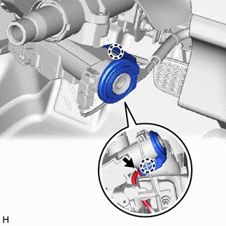
Disconnect the connector.
-
Disengage the 2 claws and remove the transponder key coil.
-
- Click here
REMOVE TURN SIGNAL SWITCH ASSEMBLY WITH SPIRAL CABLE SUB-ASSEMBLY
Note:
-
Do not remove/install the spiral cable with sensor sub-assembly with the battery connected and the ignition switch ON.
-
Do not rotate the spiral cable with sensor sub-assembly without the steering wheel assembly installed, with the battery connected and the ignition switch ON.
-
Ensure that the steering wheel assembly is installed and aligned straight when inspecting the steering sensor.
-
Disconnect each connector from the turn signal switch assembly with spiral cable sub-assembly.
-
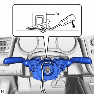
*a Clamp Using pliers, expand the clamp.
-
While holding the clamp expanded, raise the claw using a screwdriver to disengage it, and then remove the turn signal switch assembly with spiral cable sub-assembly from the steering column assembly.
-
- Click here
REMOVE LOWER NO. 1 INSTRUMENT PANEL AIRBAG ASSEMBLY
- Click here
REMOVE NO. 1 AIR DUCT (for LHD)
-
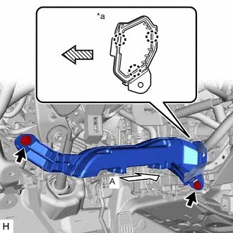
*a View A 
Front Remove the 2 bolts.
-
Disengage the 3 claws to remove the No. 1 air duct.
Note:Be careful not to deform or damage the lower heater case of the air conditioner unit assembly when removing the No. 1 air duct.
-
- Click here
REMOVE NO. 1 AIR DUCT (for RHD)
-
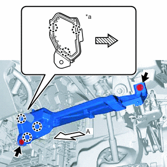
*a View A Front Remove the 2 bolts.
-
Disengage the 3 claws to remove the No. 1 air duct.
Note:Be careful not to deform or damage the lower heater case of the air conditioner unit assembly when removing the No. 1 air duct.
-
- Click here
REMOVE FRONT WHEEL LH (for LHD)
- Click here
REMOVE FRONT WHEEL RH (for RHD)
- Click here
SEPARATE STEERING INTERMEDIATE SHAFT ASSEMBLY
- Click here
REMOVE STEERING COLUMN HOLE COVER
-
Turn back the floor carpet.
-
Remove the clip.
-
Disengage the 2 clips to remove the steering column hole cover.
-
- Click here
REMOVE STEERING INTERMEDIATE SHAFT ASSEMBLY
-
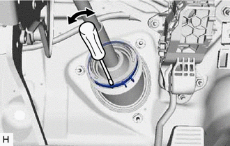
Using a screwdriver, loosen the clamp as shown in the illustration.
-
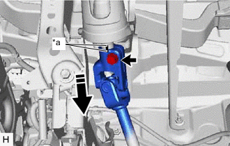
*a Matchmark Remove the bolt and slide the steering intermediate shaft assembly.
Note:Do not remove the steering intermediate shaft assembly from the steering column assembly.
-
Put matchmarks on the steering intermediate shaft assembly and steering column assembly.
-
Remove the steering intermediate shaft assembly from the steering column assembly.
-
- Click here
REMOVE STEERING COLUMN ASSEMBLY
-
Disconnect each connector and disengage each wire harness clamp from the steering column assembly.
-
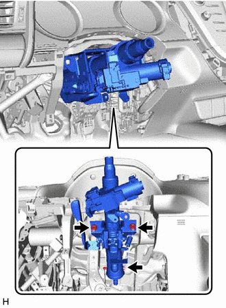
Remove the bolt, 2 nuts and steering column assembly.
-